I was looking for some animations of dml panels and came across this YouTube of tectonic speakers.
Also this underground station test, although this could just be because of more speaker, they do not show the old and new setup ?
how many times have I stood on an underground or train station ,and not understood a word they were saying !!!
Steve.
Christian.
over the years I have done many tests using different sizes of blu-tack blobs and crosses ,to prevent standing waves within the coil area.
this can be quite successful but the effect on the sound of the panel because of the weight is not good.
I would describe it as a slowing down of the sound or over damping.
in your plot up to about 3.5k there is a mirroring of responses but at a lower level(general damping) above this it all starts going awry.
Weather this is because of the random pieces stuck to the central area as in your photo I don't know ?
I usually use single different sized blobs for my tests for consistency.
But I did notice something you might find interesting , in your previous attachment but I need to go on the computer to look at it again.
If I have to use damping ,this usually means the panel or exciter has a problem, and if too much damping is used , the panel starts to sound more like a cone type speaker.
To my ears,anyway ?
Steve.
Christian.
Ok ,I have just had a look at the additional mass plot.
i recognise some of the traits from my tests ( from memory ) .
I will stick to two plots ,the pink and green 1.6g as these are the most relevant to me.
in the green plot you will see that the peak in the 10k area has reduced a little ( this peak can be much larger on some panels) but below this frequency the suck out has been reduced as well !
the geen plot would be my preferred line, also usually the dip in the response after the peak usually comes up a little, but im wondering if the fact that the blu-tack ? is a flat disk is preventing the HF above this from happening ?
i used to use a very small blob of blu-tack in the centre of the exciter coil area to prevent standing waves ? in the coil foot area.
this would prevent large peaks and troughs in this area ,but this would also reduce the life and dynamics a little.
so the plot says YES , but my ears say NO.
I also see a tell tale hump in the 2.5k area this is probably the cavity behind and in the coil area ,letting itself be known ? these two peaks are my main bugbear with standard exciters(and im sure with standard cones and tweeters ).
getting rid of these two peaks does clean up the sound of the panel and prevents the panel from sounding so shouty sometimes, mainly on vocals I notice this.
hope you find these observations interesting .
steve.
@spedge
This afternoon, I was in my garden for some outdoor measurements. The conditions were perhaps not optimum : cold (5 to 7°C), this garden is small surrounded by fences and hedges 2m high (see pictures). Nevertheless what I did is to measure the canvas and plywood panel on each side : front, left, right, back. For the plywood, as the panels are supported along the 3-way speakers in the living room, I have no support, no stand for them. Outside, I need a small angle to avoid having them pushed by the little wind. At low frequencies, they moved a little from their position on the tretles with a little noise.
The graphs are below.
I will try to put them in a document. IR and spectrogram are available. Let me know if you want something. I have added a comparison of the outdoor and indoor
What I see :
Christian


This afternoon, I was in my garden for some outdoor measurements. The conditions were perhaps not optimum : cold (5 to 7°C), this garden is small surrounded by fences and hedges 2m high (see pictures). Nevertheless what I did is to measure the canvas and plywood panel on each side : front, left, right, back. For the plywood, as the panels are supported along the 3-way speakers in the living room, I have no support, no stand for them. Outside, I need a small angle to avoid having them pushed by the little wind. At low frequencies, they moved a little from their position on the tretles with a little noise.
The graphs are below.
I will try to put them in a document. IR and spectrogram are available. Let me know if you want something. I have added a comparison of the outdoor and indoor
What I see :
- At 90°, the level increases when the frequency increases (3dB/oct?)
- For the canvas, the levels on the sides remain lower than the front/back by 5dB. Not for the plywood.
- For the canvas, the peaks seen indoor at 380Hz and just before 800Hz (760Hz?) are visible outdoor which invalid my 1st idea it was a reflection.
- There is a peak near 2k/3k on the back wave for both. Very important for the plywood (some resonance of the spine?)
- Both panels have a loss in low frequency indoor compare to outdoor
- Below 200/300Hz both panel suffer from the lack of some frequencies (not so strange for a DML)
- Above 200/300Hz, the plywood seems more flat.
- For the canvas, there is a loss in the high frequencies for the rear wave. This is not visible on the plywood despite a more important mask.
- The plywood rear wave is not as flat as the front (effect of the spine?)
Christian
Thank you SteveChristian.
Ok ,I have just had a look at the additional mass plot.
i recognise some of the traits from my tests ( from memory ) .
I will stick to two plots ,the pink and green 1.6g as these are the most relevant to me.
in the green plot you will see that the peak in the 10k area has reduced a little ( this peak can be much larger on some panels) but below this frequency the suck out has been reduced as well !
the geen plot would be my preferred line, also usually the dip in the response after the peak usually comes up a little, but im wondering if the fact that the blu-tack ? is a flat disk is preventing the HF above this from happening ?
i used to use a very small blob of blu-tack in the centre of the exciter coil area to prevent standing waves ? in the coil foot area.
this would prevent large peaks and troughs in this area ,but this would also reduce the life and dynamics a little.
so the plot says YES , but my ears say NO.
I also see a tell tale hump in the 2.5k area this is probably the cavity behind and in the coil area ,letting itself be known ? these two peaks are my main bugbear with standard exciters(and im sure with standard cones and tweeters ).
getting rid of these two peaks does clean up the sound of the panel and prevents the panel from sounding so shouty sometimes, mainly on vocals I notice this.
hope you find these observations interesting .
steve.
My intention for now is not to use local mass. Pure opinion from my side : they have a reactive (in the way an inductance has) nature. This test was more to see how a DML is sensible to the mass as predicted by the simplest equivalent model.
The reason your hears don't like the effect of mass is perhaps in phase or time change they cause : delay and energy coming back later?
I note the 2 peaks you mention : 2.5k and 10k and you already know. This means they are intrinsic to the panels. To have a design to avoid them would be great but what about simply a bit of EQ to reduce them.
In the post with the outdoor measurements, we can see the peak at high frequency is higher (about 16k) for the plywood
In fact, the plywood suffers from less peaks... but in the spectrogram view less time aligned than the canvas. I think my next step before going for irreversible modifications of the canvas is to test some EQ.
Most of the designs use the exciter/membrane interface as provided with the exciters : double side tape or glue at the edge of the voice coil. Do you know if other interfaces were tested? for example as in 1st approach the mass is not a big issue an additional coupling part like an extremely rigid and damp dome?
Christian
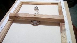
Christian,Detail of the exciter immobilization (the exciter is bold on the square plywood piece, wooden blocks help to keep it parallel to the membrane while the filling material is applied). Adaptation of what I understood from Zygadr at Audiocircle. This is an intermediate step, the cable has to go through the square base before applying the filling material.
View attachment 1017868
With the filling materail (I thought I bought some silicone but in fact it more hard more similar to plaster!)
View attachment 1017870
Thanks, especially for the details about your exciter mounting. I may have seen Zygadr's post about that method at some point, but I did not recall it.
Eric
Below what is in my notes from Audiocircle thread (when I took those notes, I didn't keep the exact source...)Christian,
Thanks, especially for the details about your exciter mounting. I may have seen Zygadr's post about that method at some point, but I did not recall it.
Eric
So the method on my panel is more rigid keeping the idea of no effort on the exciter by the mounting method.
The foam at the back of the exciter shown by Toddincabo #4328 is more close to Zygadr's idea.
My measurments on the plywood panels shown a distortion reduction with the brace (spine). My last outdoor measurements shown also an unexpected peak on the back side around 2k. This has to be investigated.
From Zygadr Audiocircle :
The trick here is to fill in the space(and there must be a space of around 1/2 inch) between the exciter's back and wooden brace with silicone.
This does not place any undue pressure on the exciter.
When the silicone dries, it simply forms a cushion (and holds it in place to the brace) or back compliance to the exciter if it plays any severe low bass notes such as a bass drum whack.
Naturally you would not want to apply any pressure to the back of the exciter as does the plastic housing
Christian.
the plots look pretty familiar to me, the in house and garden seem to follow each other well, except at the low end,but this is to be expected with room modes, not forgetting these are single point measurements and they could change within a few hundred mm in the room.
you are using 5db steps which is the same as I use for testing.
others use 10db or 20db steps and if you used these steps they would be saying WOW look at that flat frequency response !!
the two peaks are not intrinsic to the panel ,they are caused by the exciter design.
You cannot EQ the noise caused by the exciter without putting huge dips in the music.
I used a notch filter to trace the noise in the 2k to 3k area using pink noise and switched it in and out to compare the sound.
It was a vast improvement but not a good idea for the music, it's far better to sort it out at source.
as for ziggy ,I don't remember him being much of a fan of spine bracing ,but I am sure there were some others that used this method, this thread was trying to make a sort of podium clone to start with , I think ?
I use far simpler methods.
Steve.
Yes 5dB steps is a kind of rule for me now even if the curve is not pretty flat!Christian.
the plots look pretty familiar to me, the in house and garden seem to follow each other well, except at the low end,but this is to be expected with room modes, not forgetting these are single point measurements and they could change within a few hundred mm in the room.
you are using 5db steps which is the same as I use for testing.
others use 10db or 20db steps and if you used these steps they would be saying WOW look at that flat frequency response !!
the two peaks are not intrinsic to the panel ,they are caused by the exciter design.
You cannot EQ the noise caused by the exciter without putting huge dips in the music.
I used a notch filter to trace the noise in the 2k to 3k area using pink noise and switched it in and out to compare the sound.
It was a vast improvement but not a good idea for the music, it's far better to sort it out at source.
as for ziggy ,I don't remember him being much of a fan of spine bracing ,but I am sure there were some others that used this method, this thread was trying to make a sort of podium clone to start with , I think ?
I use far simpler methods.
Steve.
I see my wording was not precise enough. By intrinsic to the panel, my intention was to say link to the loudspeaker (membrane, exciter, brace... any component) and not link to an interaction with something outside of this system like a surrounding wall.
For now, I don't have the maturity or experience to understand why we can't EQ those peaks. They are linked to the exciter, seem not delayed from the main signal front... For sure it would be better to sort them at source.
About audiocircle thread, yes it is probably at the beginning of the thread (as it is at the beginning of my notes).
I am sorry not having notes from your methods for bracing (or not?)... so if you have in mind a post (or a period) about it, please!
Christian
@spedge
The back side outdoor measurement of my plywood panel let me puzzled with the 2k peak (see #4404)
So I did some more measurements.
At 50cm in indoor conditions, the peak is confirmed.
So I did some proximity measurements to see if it is possible to point on the source of the peak. In addition of the standard logsweep, I have generated a narrow band pink noise aroound 2k (REW has many usefull functions! yes!) and search for the position of highest SPL. I suspected an effect of the rear brace stiffness but I found nothing (nothing obvious!) around that.
But it seems the level just at the end of the square plywood piece supporting the exciter is high (red arrow below).
In the same idea, there is a high level at 10k just at the exciter hole (green arrow).
The square piece side is 10cm so 5cm from center to edge which leads to 1750Hz has lambda/4 (quarter wavelength) for a peak at 1850Hz in REW. Right explanation or coincidence ? The fact is, I check it again today, the canvas panel which doesn't have this square piece has not this huge peak.
What is your opinion ?
Christian
Green line, a very flat response from 200-1000hz. The region I had in mind for the dml in a 2-way satelite with a StageAccompany planar tweeter 1000hz and up. OB 18” woofer for bottom part.@spedge
The back side outdoor measurement of my plywood panel let me puzzled with the 2k peak (see #4404)
So I did some more measurements.
At 50cm in indoor conditions, the peak is confirmed.
So I did some proximity measurements to see if it is possible to point on the source of the peak. In addition of the standard logsweep, I have generated a narrow band pink noise aroound 2k (REW has many usefull functions! yes!) and search for the position of highest SPL. I suspected an effect of the rear brace stiffness but I found nothing (nothing obvious!) around that.
But it seems the level just at the end of the square plywood piece supporting the exciter is high (red arrow below).
In the same idea, there is a high level at 10k just at the exciter hole (green arrow).
The square piece side is 10cm so 5cm from center to edge which leads to 1750Hz has lambda/4 (quarter wavelength) for a peak at 1850Hz in REW. Right explanation or coincidence ? The fact is, I check it again today, the canvas panel which doesn't have this square piece has not this huge peak.
What is your opinion ?
Christian
View attachment 1018392
Now I feel intrigued to pursuit that thought!
Pepe,Green line, a very flat response from 200-1000hz. The region I had in mind for the dml in a 2-way satelite with a StageAccompany planar tweeter 1000hz and up. OB 18” woofer for bottom part.
Now I feel intrigued to pursuit that thought!
I am perhaps posting to many measurements? Be careful with this last measurements, the mic was about 1cm from the position pointed by the arrows; the objective is to understand a strange behavior seen before. That said, you can have ideas of panel performances in the posts before (for example #4404) and many others before
The DML have several typical characterics. One is the capability to go down with not a so big surface (see the canvas type before). An other is their low directivity... so I not sure they will match with tweeter like planar. I suggest to ask to more experienced DML builder before going in this way (that said, any experience is good). In addition a DML, depanding on the design, basically doesn't suffer from a lack of treble (ok I am not so young!). The most common use is 200Hz to 15kHz or around with a woofer below. for now I have no sub, the DML play full range not badly.
Christian
I can see that I got a bit carried away. Didnt read that thoroughly at first.Pepe,
I am perhaps posting to many measurements? Be careful with this last measurements, the mic was about 1cm from the position pointed by the arrows; the objective is to understand a strange behavior seen before. That said, you can have ideas of panel performances in the posts before (for example #4404) and many others before
The DML have several typical characterics. One is the capability to go down with not a so big surface (see the canvas type before). An other is their low directivity... so I not sure they will match with tweeter like planar. I suggest to ask to more experienced DML builder before going in this way (that said, any experience is good). In addition a DML, depanding on the design, basically doesn't suffer from a lack of treble (ok I am not so young!). The most common use is 200Hz to 15kHz or around with a woofer below. for now I have no sub, the DML play full range not badly.
Christian
Hi Christian .
This is a picture of my canvas panel without a ply panel in the middle.
I had to use the spine to support the exciter on the canvas.
It is all glued together with pva, and causes very little obstruction to The rear wave from the panel.
The flat piece of board you are using close to the panel to support the exciter is probably making the cavity resonance much worse and causing its own resonances .
I never did like The look of those 4 mounting holes on that exciter and would not use them myself.
The whistling from the vent hole in the magnet is part of the coil cavity resonance, stopping the coil cavity resonance will stop this noise.
If you cup your hand over the back of the magnet area while playing pink noise you will make the noise even louder
You cannot EQ these problems away as they are not part of the music signal , they are a distortion , made by the exciter itself.
If the voice coil for instance was miss aligned and was rubbing on the magnet ,you could not EQ this noise out either, not without destroying the original music signal.
Does this help your understanding of the problem ?
If not maybe you should read the phase plug forum I posted , this is the same problem.
Steve.
Attachments
Christian.
I just remembered I made a recording of the 2.5k noise on page 189 post 3767 and me using the notch filter to cancel it.
Steve.
I just remembered I made a recording of the 2.5k noise on page 189 post 3767 and me using the notch filter to cancel it.
Steve.
Christian.
also on post 3727 there are plots of the front and back of one of my panels showing the problem clearly.
Steve.
also on post 3727 there are plots of the front and back of one of my panels showing the problem clearly.
Steve.
Chistian.
there are more informative plots in post 3732 .
I have said many times in the past about this problem ,but I get no feedback , so I presume it is just ignored !!
I prefer to fix the problem and enjoy the music 😁
Steve.
there are more informative plots in post 3732 .
I have said many times in the past about this problem ,but I get no feedback , so I presume it is just ignored !!
I prefer to fix the problem and enjoy the music 😁
Steve.
I have not seen this model bmr before and the discussion is interesting.
I'm not keen on damping but I think with this type of driver there is not much choice ?
But it obviously works to cure the problems.
Steve.
These are basically my exciters, the design has not changed much over the years ?
Steve.
https://www.tectonicaudiolabs.com/product/teax25c10-8-hs/?id=product-794
Steve.
https://www.tectonicaudiolabs.com/product/teax25c10-8-hs/?id=product-794
Hello SteveChistian.
there are more informative plots in post 3732 .
I have said many times in the past about this problem ,but I get no feedback , so I presume it is just ignored !!
I prefer to fix the problem and enjoy the music 😁
Steve.
Thanks a lot again for all your support. You are extremely patient to answer to all our questions, finding previous posts. It is really very nice.
If it can help for next new comers or even for you, I store those information in the "history file". I will attache a new version in some posts.
For your brace technique : yes is it more simple than what I did. I just understood from my last measurements and from your feedback that I have built a kind of "flat horn" that amplifies the 2k peak! So one action should be to modify it. The strange side is that I designed those panels with the idea having a low depth. Strange idea indeed because it leads to surfaces not correctly oriented, neither for the sound, neither for the inertia against the exciter movement. I will also think to add a spine to the canvas. It should help.
About the exciter you use, I have found few differences compare to the Dayton Audio DAEX25FHE-4. About the same dimensions. Lower voice coil mass and higher BL in favor of the Tectonics but lower power handling (does it really matter the power above 10W?). In this category of exciter, the Dayton Audio is the only one available where I order.
The main topic is about the peaks. Be sure what you wanted to mention in the post 3732 has now an echo to me! Perhaps not surprising you had no feedback at this time, the discussion was oriented on the membrane material and the focus of any DML builder is first on the membrane, not on the exciter/membrane interface... From my side it took time I understand it is not a problem of the panel in the room but something inside it, in its components and design. My understanding was also not tune on your words "cavity", "noise". So now it is.
I am a bit surprised not being really annoyed by those peaks. According to what I read (ie M Floyd Toole), peaks are not good!
Do you have identified the mechanism of those peaks? I understand the possible trouble in the voice coil area with the central point where all the waves converge. I can relate it to the 9/10k peak. For the 2/3k peak I am a bit perplex. Is it a phenomena of the air pinched between the membrane and the spider (the area I increase in the plywood version!)?
About the counter measure, you have experimented the added mass (a cross). I understand the dome is also in this category. Is it also a solution against the 2/3k peak?
I have some ideas to experiment... but I would prefer to test before sharing. For that, I think to start for a new pair of panels (I have a third pair of exciters available). I would like to keep a width about 30/33cm (more suitable for a living room). The height is not a big criteria until I have the possibility for a woofer (probably an old 21cm I have also) at the bottom and a total about 1m. For an user use, something like 55cm high is good (the woofer will be than a little bit aside). For the bandwidth, something similar to the plywood panel (fo about 50Hz). I would prefer to test something else than canvas or plywood. With your indication to previous posts, I see EPS (not XPS as I already experienced and won't go again) is in good position in the material ranking. Do you have advice in addition to that... if possible not too exotic?
You have used very often EPS. HD EPS meaning some thing like 30kg/m3? If I remember in 10mm. Do you have any indication of bending stiffness (in the way we share with Veleric some posts before like 4185)? I would be nice to input them in the material graph.
Christian
Last edited:
- Home
- Loudspeakers
- Full Range
- A Study of DMLs as a Full Range Speaker