Hello AndréChristian, I'm not sure that one can determine whether an open-back DML panel is strictly a dipole in the classical sense simply by taking directivity responses. A dipole is a dipole because front and rear waves cancel out at the edges at the relevant frequencies, but I don't think that's everything that's happening with a DML panel. If one looks at high-order modes at higher frequencies on a DML panel, then it's clear that there are multiple "micro-diploes" operating simultaneously, any one of which will be in or out-of-phase with its neighbouring dipoles and obviously out-of-phase with its own wave on the opposite face of the panel (but which will be acoustically isolated because of the size of the panel relevant to the acoustic wavelengths.)
Any one "micro-dipole" on the front of the panel will simultaneously have an IN-phase micro-dipole operating on the rear of the panel. Which makes it a micro-BIpole...
So, as far as the whole panel is concerned, I think we might be looking at a diffused BiDipole? ... 😎
My sentence was probably not precise enough. My opinion is a DML with an open back is much close to an open baffle than I thought. A kind of variant. I agree that a big difference between a DML and a standard open baffle is that the sources of sound move with the frequency according to the modes so the way they combine front and rear may be different from a standard baffle and with the frequency. What I think, it is visible from the directivity plots, is a behavior close to an open baffles in the first modes giving a peak, a first null and then 4 and 6 lobes. After, it seems there is tendency of higher SPL in the angles above 60°. Of course take that with a bit of salt... It is too recent observations to be a conclusion. The influence of the edge conditions might have a role too.
Anyway, I think the careful approach is to think them as DML (for the mode aspect) and as a dipole (for the front and rear cancellation) in order to give the right cause to the peaks and dips we see in the FR.
The on axis peaks and dips, the lobes are visible. The question is "is it important in the final result?"
I have the idea to add a kind of "dipole behavior detection" in my script that plot the directivity map as I have implemented a coincidence frequency detection. Not done for now, I have switched to the concentrator topic because I think the cavity noise comes before in the list of things to improve.
The dipole approach could also change the target of the "pure" DML FR (I mean the FR in a half space with no effect of the back as Dave shows it in his simulation tool) in order to combine it more nicely with the diffuse dipole FR.
Below are 2 polar plots of the same panel I use for test (30x40cm clear polystyrene, I think close to acrylyc). There is a peripheral suspension and a frame.And I also think that the edges of a panel reveal an acoustic null because the surface waves cannot project in-line with the plane of the panel, and maybe because the individual micro-dipoles do short-circuit at the edges? Also, the relevant micro-dipoles might only be active closer to the exciter than they are to the edges anyway, depending on the damping factor of the panel itself.
It is plotted with and equalization of the +/-20° listening window (on axis).
In the left, it is in the open back conditions. The null at 90° is clearly visible (also some 30 to 50° lobes and the cavity noise at the rear)
Right is the same with a thick absorber on the rear and then a plate. It is not a closed box, the sound can probably escape from the sides of the absorber. Nevertheless, it seems the sound is able to go more than 90° when the frequency decreases. The cavity noise is absorbed, the front lobes are reduced also (is it their DML part remaining?).
Nothing say it is better or not for music! It was just a measurement to get an idea to what change when the rear wave is attenuated.
I have no measurements from a closed box or some quasi infinite baffle. To set the right volume for a closed box needs some investigation. All the tentative to close in a small volume (a back plate right behind the panel) leads to a huge peak in the FR.

Indeed I have not tested the plates at that distance, but have not noticed that HF drops off faster by distance compared to a regular speaker. I have been setting up a bit larger than 20x20m, but never more than 15 meters to closest speaker. For example JBL recommend for club installs to have one stack in each corner up to 100m2, then you need to start adding treble fills from above. At above 200m2 you should start adding mid fills on the sides.Leob is that maybe because use set up your system all around your dance-floor listening area? Iif so, then I'd assume that the maximum distance, ear-to-speaker, might be no more than 5metres or so for a 100sqm dancefloor?
When I run my panels outdoors, I sometimes have to project over 20 or 30m to the furthest seats, and they do end up sounding a bit dull.
For a stage, I think at 10kHz you should expect around 1dB more loss per 10m, so at 30m it should be down by around 3dB, so about where you might start thinking about having delayed stacks to fill up the back if the area would extend even further. How much faster you think the DML will decay at 10KHz?
Considering that traditional tweeters tend to be much more directional, unless it is a very significant difference in decay I would think that in general over the whole audience you still have a more even FR?
Also, how high up are you mounting the plates? Since tweeters will radiate from a small source, typically placed above head height of the audience, you will get more of the power in the back than if you have a plate party obscured and running the energy into the ground instead of the air. To project all the energy that far back, I think the plates would have to be mounted very high, basically so the bottom of the plate is where there tweeter would be otherwise.
Leob...refer to your point 1 in this post...
Thread 'DML PA systems' https://www.diyaudio.com/community/threads/dml-pa-systems.390363/
Thread 'DML PA systems' https://www.diyaudio.com/community/threads/dml-pa-systems.390363/
Yes, that is my experience in general when running four stacks in a rectangle. But that does contradict Andres experience. It might be the case that for some reason the diffuse waves cancel out HF more at a distance. Say the decay rate at 10kHz was as extreme as double of a regular speaker. In that case, at 10M it would be -2dBSPL, so not very noticeable on a 20x20m dancefloor or when testing response at a few meters.
Having said that, that point in the PA thread was based on subjective experience reported by many, but doing point measurements I'm not so sure. And of course it is quite an extraordinary claim, since it does seem to defy physics, but I guess you can view a DML as a small line array since it in fact creates an array of emitting nodes.
Here are the of axis measurements from my first revision at 1,2 and 4m. Not a great response, and with exactly the problem around 10k that Andre mentioned. I took the off axis response since it is more even and easier to compare relative amplitude:

Comparing the 1 and 4m curves, it looks like to me that in most of the spectrum the difference is around 10dB instead of the expected 12dB. If that holds true for the next doubling as well, that would mean 4dB more from the speaker in the middle of the dancefloor if it is 16x16m, which I guess would be quite significant. Surely someone must have made better measurements that can confirm if it is really the case?
But for HF decay over distance, apart from needing a plate that actually has decent HF reproduction, I would need to measure from much further away since at 4m the difference would be fractions of a dB anyway.
Having said that, that point in the PA thread was based on subjective experience reported by many, but doing point measurements I'm not so sure. And of course it is quite an extraordinary claim, since it does seem to defy physics, but I guess you can view a DML as a small line array since it in fact creates an array of emitting nodes.
Here are the of axis measurements from my first revision at 1,2 and 4m. Not a great response, and with exactly the problem around 10k that Andre mentioned. I took the off axis response since it is more even and easier to compare relative amplitude:
Comparing the 1 and 4m curves, it looks like to me that in most of the spectrum the difference is around 10dB instead of the expected 12dB. If that holds true for the next doubling as well, that would mean 4dB more from the speaker in the middle of the dancefloor if it is 16x16m, which I guess would be quite significant. Surely someone must have made better measurements that can confirm if it is really the case?
But for HF decay over distance, apart from needing a plate that actually has decent HF reproduction, I would need to measure from much further away since at 4m the difference would be fractions of a dB anyway.
@Andre Bellwood , @Leob
Can this help in the topic : Absorption of sound by the atmosphere
I am maybe not fully in the topic as it doesn't explain the difference with a standard loudspeaker.
Christian
Can this help in the topic : Absorption of sound by the atmosphere
I am maybe not fully in the topic as it doesn't explain the difference with a standard loudspeaker.
Christian
Hi Christian,
This touches upon a thing I have been wondering about "normal" speakers : how can the broad spreading of the woofer combine with the narrow beam of the horn.
As PA speakers usually have some kind of horn for the HF, it could well be that the bundling of the HF (as opposed to the semi-omni low freq radiation) makes up for the HF air damping. And thus give a somewhat balanced response over the normally used distances.
Hans
Thanks, yes it depends on temp and humidity, so the figure of 1dB per 10m would be at 80%RH and 20C, at 50%RH it goes up to 1.6dB.@Andre Bellwood , @Leob
Can this help in the topic : Absorption of sound by the atmosphere
I am maybe not fully in the topic as it doesn't explain the difference with a standard loudspeaker.
Christian
This forum is SUCH an enormous source of very excellent comment and observation.
Thank you Gents.
Thank you Gents.
Christian,In the left, it is in the open back conditions. The null at 90° is clearly visible (also some 30 to 50° lobes and the cavity noise at the rear)
Can you share the on-axis front and back measurements (i.e. 0 deg and 180 deg) for the acrylic panel shown in your open back measurements? I'd like to get a better sense of the magnitude of the "cavity noise" you are seeing. I presume that what you are calling "cavity noise" is the red at 3 kHz, is that correct?
I have not made a lot of back measurements, but just yesterday I made several on various panels (not acrylic) with the 25FHE exciter. In those measurements, I did see a difference between the front and back at 2-3kHz, but not more than about 5 dB in any case. Are you seeing more difference than that?
Eric
Hello Eric,Can you share the on-axis front and back measurements (i.e. 0 deg and 180 deg) for the acrylic panel shown in your open back measurements? I'd like to get a better sense of the magnitude of the "cavity noise" you are seeing. I presume that what you are calling "cavity noise" is the red at 3 kHz, is that correct?
I have not made a lot of back measurements, but just yesterday I made several on various panels (not acrylic) with the 25FHE exciter. In those measurements, I did see a difference between the front and back at 2-3kHz, but not more than about 5 dB in any case. Are you seeing more difference than that?
I have added a "feature" in the plots from the directivity measurement which shows the frequency response from the rear side along with the FR of the listening window and the directivity index. It is the mean SPL value over +/-40°. Below is the clear polystyrene (close to acrylic), below is the 2mm plywood and next is a 20mm EPS.
The red dashed line is the rear.
The amplitude of the "cavity noise" is here about +10dB. It is from exports of REW smoothed at 1/24 of octave, at 1m. The FR is gated at 5ms. After a quick check, the amplitude difference seems not change a lot with the smoothing... This amplitude is in the FR 180° compare to 0°.
I don't have 360° measurement for the poplar plywood 3mm (test panel) but I have the front and rear of my current 3mm poplar plywood panel made 2 years ago. They show also a peak 2kHz/10dB.
It seems there is a constant here at about +10dB with some difference in frequency according to the material.
Is the air here different from yours? ;-)
Or like for the trains, one noise can hide another one (it was the warning at the railway crossings here.).
Anyway, something happens on the search of this. Let's hope now to find a good counter-measure!
Christian
PS
Something I haven't notice yet from those plots, o the rear, above the 2/3k peak, in the 5 to 10kHz, there are differences... for the clear polystyrene (let me know is there is a more appropriate name for it) there is no spine, for the plywood there is a vertical spine about 5cm wide in contact with the exciter, for the EPS is a 2cm vertical tube but maybe 5cm behind the exciter. For the 2 last one it is like they created a mask...
The shape, the position of the spine might be to consider.
Clear (glass) polystyrene
Basswood 2mm plywood
EPS 20mm
Christian, if you think the noise is emanating from the exciter, how about trying a cup type device stuffed with sound absorbing material immediately surrounding the exciter to see if it reduces/ eliminates the problem
Harking back to an old post of mine, I used a felt flap to do the same thing.
Also, venting the connection of the exciter to the panel will reduce/eliminate pistonic pulsing within the coil area which may be causing the noise through the magnet vent.
Eucy
Harking back to an old post of mine, I used a felt flap to do the same thing.
Also, venting the connection of the exciter to the panel will reduce/eliminate pistonic pulsing within the coil area which may be causing the noise through the magnet vent.
Eucy
Last edited:
Hello Eucy. Yes it is the source. This solution is in my listChristian, if you think the noise is emanating from the exciter, how about trying a cup type device stuffed with sound absorbing material immediately surrounding the exciter to see if it reduces/ eliminates the problem
This one also. I remember your post about that. For now I was testing more at the source like with a concentrator with holes.Harking back to an old post of mine, I used a felt flap to do the same thing.
I don't understand "venting the connection...". Could you explain a bit more or differently please?Also, venting the connection of the exciter to the panel will reduce/eliminate pistonic pulsing within the coil area which may be causing the noise through the magnet vent.

Guys, I battle to get my head around this idea of "cavity noise." Is it actually "noise", in the sense of white noise/pink noise? or is it a cavity resonance. If it's resonance then, yes, I have also picked up this issue especially when using those screw-adaptors that increase the length of the cavity. For this very reason I have done some experimentation with felt pads inside the cavity, and also measurements with holes cut into the panel in front of the cavity. That was a long time ago. If I find them I'll post.
I think the best way of addressing the problem is actually to put some kind of vent hole through the magnet itself.
It appears that the manufacturers are not aware of the problem??
I think the best way of addressing the problem is actually to put some kind of vent hole through the magnet itself.
It appears that the manufacturers are not aware of the problem??
I am also trying to understand this better. Is cavity noise or resonance a problem? Can it be heard or only shows up in measurements?
André, it looks like a hole in the panel does not solve the issue, but instead creates a bigger one. See your post here:
The red curve is with the CD untouched.
The blue curve is with the hole sealed with hard, light plastic and superglue.
The hole causes a massive notch at 1.2khz.
But it...
And it seems damping the inside cavity did not help either. See this post:
Damping this cavity had no effect, whereas the Dayton Megabass (DAEX 32QMB) which had a 7kHz peak on Twinwall, did benefit greatly from a thick felt plug inside the VC cavity.
André, it looks like a hole in the panel does not solve the issue, but instead creates a bigger one. See your post here:
Here's the ($26-00!) DAEX30HESF-4 on a CD. That's the CD disc itself with the 15mm hole in the middle...I should fess up, I did the same with a cd case. Felt sure I would get some HF with the DAEX19-CT4 exciter. Nope. But if memory serves, not as bad as XPS.
Typical Ben channel on youtube got what seemed to be excessive HF with the dayton thruster on acrylic. Seems to be a resonance effect, but if that works....
The red curve is with the CD untouched.
The blue curve is with the hole sealed with hard, light plastic and superglue.
The hole causes a massive notch at 1.2khz.
But it...
And it seems damping the inside cavity did not help either. See this post:
Yes, the hole creates a notch instead of a peak. I'm sure it has something to do with the size of the VC area.Looks like the hole has an opposite effect? So, something to do with the VC area? And damping the VC cavity with felt or foam did not help either?
Damping this cavity had no effect, whereas the Dayton Megabass (DAEX 32QMB) which had a 7kHz peak on Twinwall, did benefit greatly from a thick felt plug inside the VC cavity.
If by cavity noise you are refering to the peak around 10khz, I have this on my HD Eps panels and have managed to damp it down with a small amount of epdm foam tape that I use for suspension, I put a piece approx 2cm long at the centre of where the exciter is but on the front of the panel.
I like the sound of my panels with the rear absorbant backing (they are backed with a pillow around 25mm think of fiberglass insulation), it seems to help with imaging and mitigates a lot of the rear wave reflections in my lounge that was making the sound washed out and hard to locate.
I like the sound of my panels with the rear absorbant backing (they are backed with a pillow around 25mm think of fiberglass insulation), it seems to help with imaging and mitigates a lot of the rear wave reflections in my lounge that was making the sound washed out and hard to locate.
@Andre Bellwood , @twocents , @JoskaNZ
Hello all,
Sorry for the confusion due to the words I used. I have tried to use what was in my memory from very old posts of the thread. Wrong choice!
In my understanding, there are 2 distinct questions/
Christian
Hello all,
Sorry for the confusion due to the words I used. I have tried to use what was in my memory from very old posts of the thread. Wrong choice!
In my understanding, there are 2 distinct questions/
- what I named in the recent posts "cavity noise" which is you are right a resonance of the air trapped in the cavity created in the voice coil inner volume. So a better wording might be cavity resonance. It occurs in the 2/3kHz on the rear side of the panel. From the last FR I posted it really looks like a resonance. Its amplitude remains an open question, Eric has +5dB when I see +10dB. Reading your posts and other before, no doubt it is here.
- the second is called "drum effect", a wording coming from papers (I think it was patents) external to our thread. It is the resonance (or better saying modes) of the disc of the plate inside the ring of the exciter. It occurs in the 10k range.
Christian
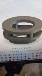
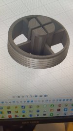
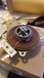
Hello Eucy,Threaded concentrator. Contact area 8x8mm
Modified from previous pic
Now down to 0.79g.
I need to remove the fine stringy bits 😊. It is printed in PETg which is prone to stringing, but it's not an issue.
Eucy
For now, I haven't posted the results from the concentrators I tested because I would like to give a picture as clear as possible... not easy.
Anyway, it seems 2 directions appear :
- A contact area in the 10mm range is a bit small from the mechanical resistance point of view (mainly for testing). From the directivity point of view, 15mm or even 20mm might be correct. At this step, the only advantage I see for a 10mm contact area is to help in creating the venting section. Not sure it really works.
- To limit the weight seems a good idea. It seems to have an influence on the 5 to 10k range.
Christian
- Home
- Loudspeakers
- Full Range
- A Study of DMLs as a Full Range Speaker