Your point being that you are unable to explain what you mean by pistonic, bending wave, and dml?Eric.
Well, there you go !
I did say from the start.
You can get yourself into a lot of trouble mentioning pistonic , !!!
Thanks everyone for proving my point 😀
Steve.
Maybe that's the reason you get yourself in trouble?
Eric
Don't you recognize marketing-speak when you read it? Gobel is trying hard to distinguish his technology so he can sell speakers for exorbitant sums.Eric.
when is a DML panel not a DML panel ?
when it is a bending wave panel 😂
I think goebel, explains it quite well.
And it saves me from getting shot down in flames again😱
He describes dml as being a resounding ,and diffused and washed out sound 😬
If there is any flack, can you point in the direction of goebel 😃
http://www.goebel-highend.de
Steve
So we are to believe that the definition of dml is "resounding, diffused, and washed out"? That does nothing to clarify our discussion.
The supposed distinguishing feature of his design, according to him at least, is that the boundaries are damped to eliminate reflections. If this definition is commonly accepted in the field (say, academic literature), I'm okay with that, but I'm not sure that it is. I doubt NXT (if it still existed) would agree, as their patents also included damped boundaries.
My interest is simply in defining our terms better, so we can at least understand each other when we say things like pistonic, bending wave, or dml. Otherwise we are speaking different languages.
Eric
"I don't know what you mean by 'glory,' " Alice said.
Humpty Dumpty smiled contemptuously. "Of course you don't—till I tell you. I meant 'there's a nice knock-down argument for you!'"
"But 'glory' doesn't mean 'a nice knock-down argument'," Alice objected.
"When I use a word," Humpty Dumpty said, in rather a scornful tone, "it means just what I choose it to mean—neither more nor less."
"The question is," said Alice, "whether you can make words mean so many different things."
"The question is," said Humpty Dumpty, "which is to be master—that's all."
Yep, quite similar. Did you find anything interesting?Pway.
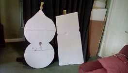
These are two very old panels I still have lying around.
Looks familiar 😁
Steve.
Seems a good choice, I would select the slow hardener. More pot time is good when you are figuring it out and I find myself spending a lot of time with the squeegee figuring it out and avoiding pools. I think the fast is only better if you are vacuum infusing or doing a lot of production where you need a piece finished quickly to move on to the next. Very new at this but that's my experience.Christian,
Look for this, or something similarly described as a laminating epoxy resin from a French supplier.
https://www.easycomposites.co.uk/el2-epoxy-laminating-resin
This starter kit is pretty cool. You could make two (pretty small) panels with this amount of material. It includes the carbon fiber, epoxy resin, release film, and PVA mold release. You would need a glass plate or mirror, and something to use as a core, like PS foam or balsa or nomex or whatever you want to try in addition to the kit. It's a cheap way to give it a try.
https://www.easycomposites.co.uk/carbon-fibre-laminating-starter-kit
Being in the US I have never purchased from them, but their videos are very good, and I expect their products are also good.
Eric

I suspect the source for the better 5 ply was a country now at war and not doing much shipping to Home Depot. 🙁...Home Depot and identically labelled as "birch plywood" but one panel was 5 ply and the other was 3 ply! I didn't even notice until I went to build the second speaker and noticed a difference in weight, and then, upon closer inspection, the difference in the number of plies. I've since gone to four different store locations looking for a panel that matches the first one, but no luck so far! The first one is more efficient than any of the plywood panels I've used before, so I'm really bummed that I can't find a matching panel.
Eric
I agree. The slow hardener. I also meant to add, it's easier and cheaper to start with fiberglass before moving to carbon fiber. Because fiberglass goes transparent when it's completely wet out with resin, it's much easier get it wet out properly. Carbon fiber is more challenging because there's no obvious clue. It helps to have done it with fiberglass first, just to get a sense of what you are trying to do.Seems a good choice, I would select the slow hardener. More pot time is good when you are figuring it out and I find myself spending a lot of time with the squeegee figuring it out and avoiding pools. I think the fast is only better if you are vacuum infusing or doing a lot of production where you need a piece finished quickly to move on to the next. Very new at this but that's my experience.
Eric
Could be. Although this was not the same "birch plywood" as what's called "Russian/Baltic Birch". That stuff is actually quite dense. The HD panels, have only a thin (maybe 10 mil) birch veneer, with some cheap and light mystery wood in between (I suspect). All the same, you could be right...I suspect the source for the better 5 ply was a country now at war and not doing much shipping to Home Depot. 🙁
I think you will find, that is called a special operation, you've got to watch what you are saying on this forum😱I suspect the source for the better 5 ply was a country now at war and not doing much shipping to Home Depot. 🙁
Steve .
Hello PaulIt doesn't help to use general terms like 'bending mode' or 'dml' to describe regimes of behaviour. But I can at least agree with Steve that there seem to be three.
(1) The low frequency regime, presumably lower than coincidence frequency, where cancellation between high and low pressure regions takes place more and more as the frequency drops, producing a declining response in the far field, or low frequency rolloff. As frequency decreases you have firstly edge and corner modes dominating, plus perhaps some remnant uncancelled 'pistonic' mode from the larger displacement near the exciter, culminating finally in the lone fundamental, most pistonic (1, 1) mode. In this regime, the antinodes are fewer and fewer, there is little overlap between resonant peaks, and you see the peaks as broad and distinct - culminating in (1, 1), the classic 'one-note bass'.
I think it could be useful to think of this regime as where the bending wave wavelength is approaching or exceeding the smallest planar dimension of the panel itself.
(2) The central regime, presumably above coincidence, where the sound waves in air are more efficiently created from panel oscillations, where the resonance peaks are many, the overlap is greater, and the far-field response reaches a peak. This is the regime that is characteristic of - the strength of - DML speakers. In this regime, the bending waves move about the panel, will reach the edges and reflect, and will find any places where standing waves are possible. This regime will have sharp, and often too-high resonance peaks, caused by specular reflections from the exciter to corners and edges, between parallel edges, or more complex combinations. It could be useful to think of this regime as being where the bending wave wavelength is smaller than the panel's smallest planar dimension, down to something like 6 times the panel thickness.
(3) The upper regime, where the bending wave wavelength is less than (say) 6 times the panel thickness, and we are approaching the limits for bending wave propagation in the panel. In this regime the energy in the wave is less, and (depending upon the material, surface, and panel thickness) it is absorbed before it reaches the edge of the panel. This has the happy coincidence that it tends to reduce beaming, and maintain the relatively more diffuse angular response that is an advantage of DML speakers.
- In all three regimes, the mode of wave propagation is the bending wave.
- Strong peaks in the upper regime could be resonance in the panel itself within the central area, with a large exciter, it could be Helmholtz resonance in the exciter cavity, or it could be break-up in the exciter mechanics.
- Membranes like art panels are definitely worth pursuing, but let's remember that they are not bending wave devices. Membranes are transverse-wave devices, they cannot support a bending moment.
Paul
I agree that canvas panel are probably of another sort due to the membrane behavior.
For the panel, the frequency range seems have different regions or regimes but I think you underestimate the coincidence frequency value. With the materials we have, the calculation of the coincidence frequency using the aerial mass and the bending stiffness leads to some kHz which means only 1/3 to 1/4 of the overall range is above.
Some months ago, I tried to make a test to evaluate the wave speed; since I have improved a little bit the treatment of such a measure. What I didn't know at this time was the wave speed is limited by the shear modulus. So probably something to retry. If you have ideas...
Fort now I would divide the FR like that :
- 1st mode frequency where the level can be not to low depending of the suspension
- the range of the modes above which are not acoustically efficient. The SPL increases with the frequency in this range
- Then is the main area which is a lot depending of the bouncing on the edge and how the suspension reacts
- From some kHz (linked to the coincidence frequency?) the level decreases like if all the surface is no more used (absorption in the panel).
- In HF, some resonances occur in the voice coil area
Christian
Hello Steve,Christian.
I know it is rather trivial , but I do not remember at any time using string to mount my panels.
the closest I've come, is using net curtain spring wire (whatever it is called) for my small but very heavy rigid ply panel.
for quick mounting I use masking tape, or for a more permanent mounting on my EPS panels I use a small sponge material which is quick and easy to hang, as easy as hanging a sock on the washing line😃
usually with panels that are lighter than the exciter I usually ,but not always, mount the exciter only ,and leave the panel free floating.
Steve.
Sorry if I mix in the same wording "string" your quick method with masking tape and mine which is kitchen string with very small clothespins. If I have time, I will compare strings and masking tape.
Reading your post I see I don't fully understand your use of sponge... A picture might be somewhere in this huge thread I guess?
Christian
Did get around to preparing the 25 kg/m2 peripor plate. I wanted to test the single exciter first, and did measurements, but after putting on the 4 exciters I realized I forgot to disable the room/speaker EQ I have on my desktop, making the single exciter readings pretty much useless 🙁 It was clear I still have the slope above 10kHz though.
With all four exciters mounted, not a big difference compared with the 20 kg/m2 styropor plate neither in efficiency or sound. The peripor sounds a bit dryer, but I think I prefer the styropor, but small differences that could be down to a little bit different exciter placement on the first plate. FR was very close to the styropor, but recorded one my desktop and other on laptop...will record both again before I remove exciters to test on new plates.
I still have to try the 10mm plates, and the neopor with the DAEX25FHE-4.
I am really happy with the performance and sensitivity of the EPS, and I think some tuning of dimensions, coating and exciter placement can make it even better. I also found how hard it is to judge or measure distortion at those levels in a small room indoors. What I do now is put a track on extremely loud and listen from another room, which has told me that I can really push the EPS with these exciters. Maybe when I try measuring with the mic at high levels, it is not the plates distorting, but the the mic.
In the end I'm not sure it will be worth the work and expense of going composite. The materials per plate will be close to €80...or if glass works out well a bit over half of that. The exciters are €16 x4 so €64 per plate.
A Neopor plate is €7.50, so €71.50 per plate in total. So the extra cost for the carbon plate means I instead could get double as many plates including the exciters for the same cost. Would of course have to be a considerable benefit in performance for it to be worth it.
And there is still the slope above 10kHz that I would like to fix but cannot figure out why I'm seeing that.
Could all three varieties of this EPS be that different from other products?
I'm using the adhesive they came with for now, and I would have thought that for example the graphs provided by Dayton also use the provided adhesive, so I doubt it is that, but will have to try to epoxy mount.
The mic seems fine when checking my active speakers and shows -2dB from 10k to 20k.
And I also doubt it is the amp, but don't have any passive speakers that I can use to test it on.
Hello again PaulAs promised, an image of my first experiment with shapes - in this case, ellipses, which I did last year. The exciter location (the dot at the centre left) is at the focus of all four ellipses. The 'baffle' is 1200x600 7mm ply (not rigid enough!) and the panel is 20mm XPS. At this point, the panel is attached to the frame with silicone sealant.
With an ellipse, any ray leaving the exciter would reflect once from the side of one of the ellipses, then through the other focus, then from the other side, or else (when the side is missing) move through to an adjacent ellipse. The ideas were to maximise randomness and asymmetry, maximise ray travel distance before reflecting back towards the exciter, minimise parallel edges and any edges perpendicular to a ray from the exciter. I also hoped that the four lobes would each resonate at a different low frequency, providing a (potentially designable/tunable) boost at particular frequencies in the bass, where modes are sparse. At the time, Id also read about acoustic black holes, and though that if you could machine an ABH at each focus, it should improve the impulse response and further eliminate reflections. Or just kill the sound completely :\
I used the term 'cusp' a couple of times above as a means to disperse a reflected ray in different directions, and people asked what I meant. The cusps are what I'm calling those pointy bits pointing inwards.
I believe that some of these ideas were supported by the tests and listening. I'll show some measurements tomorrow, not sure they show anything convincingly. Measurements were done inside. The best sound was with the panel supported as lightly as possible with little strips of foam squished into the 5mm gap between the baffle and the panel. Until it fell out, that is 🙂 There was a clear audible bass boost from the baffle.
Main problem was I didn't notice just how close the exciter came to the baffle edge, and being the 40W thruster, resonance from there was sort of inevitable. I will return to this one I think, smooth out those cusps (I think now a smooth curve is better anyway, as waves beyond a few cm would not 'see' the point anyhow), and mount the exciter more toward the centre.
Thank you. Nice butterfly!
Before reading your post, I haven't thought much more than that of the role of the corners. In my plywood panel which are currently playing I rounded the corner because statically it was part of the "standard" of the DML DIY... The only test I did was a sort of oval (4 spirals) shape which seems reinforcing some reflections. Today as a new step in the quick tests, I measured my rectangular 20x30cm test panel and then rounded the angles... the effect is much more visible than I expected. I will post FR in the next days. It adds a new parameter in the landscape.
About the role of the frame in the bass, I wonder what is acting... The frame is much less than the low frequency wavelength even the quarter wave length.
Christian
Last edited:
Steve,Eric.
when is a DML panel not a DML panel ?
when it is a bending wave panel 😂
I think goebel, explains it quite well.
And it saves me from getting shot down in flames again😱
He describes dml as being a resounding ,and diffused and washed out sound 😬
If there is any flack, can you point in the direction of goebel 😃
http://www.goebel-highend.de
Steve
The chapter technology of the link you gave is (for me) empty. I found this BendingWave : Göbel distributor
They speak about 2 kind of bending wave speaker. The ordinary one working above the coincidence frequency, their speaker working below... They point to the role of the Young modulus and the density as key factors which are clearly identified in all the paper dealing with plate vibration.With the elements I have, our panels (and even the Tectonic) seem working mainly below the coincidence frequency so for now I don't see the difference... The main point for me in the suspension which is sophisticated in the Göbel design.
Christian
Leob,Did get around to preparing the 25 kg/m2 peripor plate. I wanted to test the single exciter first, and did measurements, but after putting on the 4 exciters I realized I forgot to disable the room/speaker EQ I have on my desktop, making the single exciter readings pretty much useless 🙁 It was clear I still have the slope above 10kHz though.
With all four exciters mounted, not a big difference compared with the 20 kg/m2 styropor plate neither in efficiency or sound. The peripor sounds a bit dryer, but I think I prefer the styropor, but small differences that could be down to a little bit different exciter placement on the first plate. FR was very close to the styropor, but recorded one my desktop and other on laptop...will record both again before I remove exciters to test on new plates.
I still have to try the 10mm plates, and the neopor with the DAEX25FHE-4.
I am really happy with the performance and sensitivity of the EPS, and I think some tuning of dimensions, coating and exciter placement can make it even better. I also found how hard it is to judge or measure distortion at those levels in a small room indoors. What I do now is put a track on extremely loud and listen from another room, which has told me that I can really push the EPS with these exciters. Maybe when I try measuring with the mic at high levels, it is not the plates distorting, but the the mic.
In the end I'm not sure it will be worth the work and expense of going composite. The materials per plate will be close to €80...or if glass works out well a bit over half of that. The exciters are €16 x4 so €64 per plate.
A Neopor plate is €7.50, so €71.50 per plate in total. So the extra cost for the carbon plate means I instead could get double as many plates including the exciters for the same cost. Would of course have to be a considerable benefit in performance for it to be worth it.
And there is still the slope above 10kHz that I would like to fix but cannot figure out why I'm seeing that.
Could all three varieties of this EPS be that different from other products?
I'm using the adhesive they came with for now, and I would have thought that for example the graphs provided by Dayton also use the provided adhesive, so I doubt it is that, but will have to try to epoxy mount.
The mic seems fine when checking my active speakers and shows -2dB from 10k to 20k.
And I also doubt it is the amp, but don't have any passive speakers that I can use to test it on.
There is still a mystery for me in the HF (if it was the only one!)... With XPS 20mm, the level was to high, with the XPS 9mm in large dimension (80x60cm) I had a slope starting very early and a hump at 10k; The same XPS 9mm in small dimension (20x30cm) has a more little slope (starting later) and the same hump. For EPS, I plan to make a new test (sorry not done) but I remember also a slope...
I think Pway gave a good input saying the high frequencies don't propagate far enough from the exciter. Increasing the dimensions makes it more visible. This is an assumption. Another assumption is there is EPS and EPS (meaning different EPS). No proof but in the same time other seem happy with EPS.
I am in the opinion there is less difficulty with plywood.
An option is you make a test with plywood to see with the exciter and your amp if at least one material can go above 10k.
No need to go to a large panel. It is the HF you want to check.
My plywood panel works with the exciter with its original adhesive. I don't think this adhesive is a reason of the lack of HF... unless... The standard preparation of my panel under the exciter is first to apply some layers of watered PVA glue on at least an area of 10cmx10cm. I sand this area gently and clean it with alcohol before gluing the exciter. I can't say if it makes the difference.
Christian
Hello Paul
I agree that canvas panel are probably of another sort due to the membrane behavior.
For the panel, the frequency range seems have different regions or regimes but I think you underestimate the coincidence frequency value. With the materials we have, the calculation of the coincidence frequency using the aerial mass and the bending stiffness leads to some kHz which means only 1/3 to 1/4 of the overall range is above.
Some months ago, I tried to make a test to evaluate the wave speed; since I have improved a little bit the treatment of such a measure. What I didn't know at this time was the wave speed is limited by the shear modulus. So probably something to retry. If you have ideas...
Fort now I would divide the FR like that :
Some points in that meet what we can read about noise of a vibrating plate. It is a source to work on.
- 1st mode frequency where the level can be not to low depending of the suspension
- the range of the modes above which are not acoustically efficient. The SPL increases with the frequency in this range
- Then is the main area which is a lot depending of the bouncing on the edge and how the suspension reacts
- From some kHz (linked to the coincidence frequency?) the level decreases like if all the surface is no more used (absorption in the panel).
- In HF, some resonances occur in the voice coil area
Christian
Yea, maybe, that's why I qualified it with 'presumably' 🙂I think you underestimate the coincidence frequency
I did a simple calc last year with simple textbook equations and got around 1000 Hz I think for 3cm, which is in the ballpark, and I left it there.
To get an accurate value, you would need to use the correct higher-order theory, not the simple Kirchoff-Love theory.
Foam for example is much thicker than metal plates and deforms much more, so the poisson ratio, shear strength and deformation effects would be important. It would be nice to have it line up, but will it lead to anything you can use, practically?
I just found this paper may be of interest if you want to pursue it: https://matelys.com/publications/AMCTCG20.pdf
Christian.
There is a picture on page 266 ?
This shows my two old panels with sponge foam mountings.
This makes it easy to peg them to my lamp stands.
They do not buzz(masking tape will sometimes buzz if precautions are not taken, but is only a temporary mounting).
Steve.
There is a picture on page 266 ?
This shows my two old panels with sponge foam mountings.
This makes it easy to peg them to my lamp stands.
They do not buzz(masking tape will sometimes buzz if precautions are not taken, but is only a temporary mounting).
Steve.
What were the reasons you tried this shape ?Yep, quite similar. Did you find anything interesting?
It was a long time ago now, but I think I was trying to stop standing waves bouncing back and fourth across the panel and lessening or at least staggering ,the early reflection back to the exciter ?
There was a patent showing different shapes and their responses,but my wife deleted it from my tablet,and now I cannot find it again.
From this patent ,I placed an angled cross beam across the top of my 6ft clamped ply panel, this prevented the long decay of the low frequency resonance, or the oomph sound that carried on after the music was turned off.
I do not use a cross beam on my EPS panels but odd shapes can help.
What I remember, from the patent ,was that a panel with none parallel sides had a very similar response in the lower frequencies as the more complicated ear shape.
I think the shape you have was ok, but I do remember thinking the sound was a little thin, mainly because where the sides come in too close to the exciter , they reduce the width of the panel, hence the other panel in the photo only having small cut outs at the edges at early reflection points (even though the sides were not parallel already).
Steve
- Home
- Loudspeakers
- Full Range
- A Study of DMLs as a Full Range Speaker