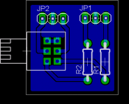
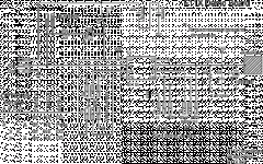
I designed this little PCB for those killer alpha pots you can get from Jaycar.
I have not tried it yet.
Mostly I wanted the board to avoid having to solder wire directly to the tiny pot, but also because I wanted a place for a resistor on input since for even some of my unity gain headphone amps some of my soures are too hot.
Cheers!
Russ
I have not tried it yet.
Mostly I wanted the board to avoid having to solder wire directly to the tiny pot, but also because I wanted a place for a resistor on input since for even some of my unity gain headphone amps some of my soures are too hot.
Cheers!
Russ
Attachments

Can you change it to have input and output jumpers, rather than left and right jumpers? Oh, and some mounting holes?
Looks good. Thanks.
Looks good. Thanks.
BrianDonegan said:Can you change it to have input and output jumpers, rather than left and right jumpers? Oh, and some mounting holes?
Looks good. Thanks.
Absofreakinglutely. 😀
needlz said:Are you using the double ganged pot for the input or 2 singles?
????
This is a double ganged pot yes.
Right... sorry... I thought you were using an alpha double ganged log pot but all I see on jaycar is the double linears.
They are 10K double gang logs:
https://secure4.vivid-design.com.au...d1=&Keyword2=&pageNumber=&priceMin=&priceMax=
https://secure4.vivid-design.com.au...d1=&Keyword2=&pageNumber=&priceMin=&priceMax=
needlz said:Right... sorry... I thought you were using an alpha double ganged log pot but all I see on jaycar is the double linears.
Its not problem, I just didn't understand the question. 🙂
Cheers!
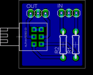
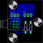
Here is an update:
Attachments
What about tightening up the layout a bit and adding mounting holes?
And we should start updating the wiki more, it seems a little out of date.
Is there a diyaudio ftp somewhere for linking to stuff on the wiki? or should we link to the forums? I would use my host, but in 5 years you'll just see 404 not found errors.
And we should start updating the wiki more, it seems a little out of date.
Is there a diyaudio ftp somewhere for linking to stuff on the wiki? or should we link to the forums? I would use my host, but in 5 years you'll just see 404 not found errors.
asgorath said:What about tightening up the layout a bit and adding mounting holes?
And we should start updating the wiki more, it seems a little out of date.
Is there a diyaudio ftp somewhere for linking to stuff on the wiki? or should we link to the forums? I would use my host, but in 5 years you'll just see 404 not found errors.
Mounting holes?
Seriously? Hadn't considered it. The PCB is just an extension of the pot. And its tiny.
BrianDonegan said:They are 10K double gang logs:
https://secure4.vivid-design.com.au...d1=&Keyword2=&pageNumber=&priceMin=&priceMax=
Ahh... didn't click on page 2 of the results. 🙂
thanks.
I was thinking of mounting the pot at the back of the amp and using a long rod to connect it to the knob. That way my inputs are nice and short and far away from the transformer. Mounting holes would make this a lot easier. Though, I could always just add extra board space for the mounting holes without it actually being part of the copper.
BrianDonegan said:I was thinking of mounting the pot at the back of the amp and using a long rod to connect it to the knob. That way my inputs are nice and short and far away from the transformer. Mounting holes would make this a lot easier. Though, I could always just add extra board space for the mounting holes without it actually being part of the copper.
Ahhh good thinking, well I hadn't planned on using like that, but I will create a second board with mounting holes. 🙂
Hi Brian you and Russ are definitely Jammin’…
I hope this is not out of context but wondering if you still think that the touch sensor QProx was still a unique idea, worth developing.
http://www.qprox.com/products/qtouch.php
I hope this is not out of context but wondering if you still think that the touch sensor QProx was still a unique idea, worth developing.
http://www.qprox.com/products/qtouch.php
Attachments
I do. The circuit is so simple. Using it to switch a power relay is super simple. De-bouncing isn;t a problem, and the toggle state is build in. I have a working test circuit for this. It consists of one chip ($.98each), a 10nF cap, a pull-down resistor and a relay.
Now, what I need is the logic circuitry for source switching. My last Digital Logic class was in 1989 or there abouts, so I am a little rusty. I plan on using the chips in pulse mode (emits a logic low pulse), one chip per source, but need the logic to turn on the source replay and release the other relays. I keep meaning to sit down and thinkit through but can't find the time. If anyone wants to pitch in, I will design and etch boards for it and get the whole thing tested. I bought 5 of the 110 chips with my last digikey order.
Now, what I need is the logic circuitry for source switching. My last Digital Logic class was in 1989 or there abouts, so I am a little rusty. I plan on using the chips in pulse mode (emits a logic low pulse), one chip per source, but need the logic to turn on the source replay and release the other relays. I keep meaning to sit down and thinkit through but can't find the time. If anyone wants to pitch in, I will design and etch boards for it and get the whole thing tested. I bought 5 of the 110 chips with my last digikey order.
- Status
- Not open for further replies.
- Home
- Amplifiers
- Chip Amps
- A simple tiny PCb for those little alpha pots