Hey Russ, you're doing a great job here. Just a couple of questions.
I like the idea of your original PCB (no mounting holes) as you can also mount these inboard inboard with a simple angle bracket and mounting the pot thgough a hole.
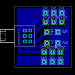
Have you made you own resistor components? The pads look bigger - for single sided use?. What size pads did you decide on and did you decrease the hole size? I'm going through the same process but haven't actually got a PCB made yet so I'm only guessing. I'd be interested in your recommendations.
I was wondering the reason of having resistors on this PCB?
BTW: The resistors look like there are off the grid a little bit.
Thanks
I like the idea of your original PCB (no mounting holes) as you can also mount these inboard inboard with a simple angle bracket and mounting the pot thgough a hole.
Have you made you own resistor components? The pads look bigger - for single sided use?. What size pads did you decide on and did you decrease the hole size? I'm going through the same process but haven't actually got a PCB made yet so I'm only guessing. I'd be interested in your recommendations.
I was wondering the reason of having resistors on this PCB?
BTW: The resistors look like there are off the grid a little bit.
Thanks
Greg Erskine said:Hey Russ, you're doing a great job here. Just a couple of questions.
I like the idea of your original PCB (no mounting holes) as you can also mount these inboard inboard with a simple angle bracket and mounting the pot thgough a hole.
Have you made you own resistor components? The pads look bigger - for single sided use?. What size pads did you decide on and did you decrease the hole size? I'm going through the same process but haven't actually got a PCB made yet so I'm only guessing. I'd be interested in your recommendations.
I was wondering the reason of having resistors on this PCB?
BTW: The resistors look like there are off the grid a little bit.
Thanks
Thanks Greg! 😀
Yes, I modified the RCL library.
I honestly can't remember what size I made those pads or the drills(did it a while back), though I think I kept the holes the same, but Here is my library for you to look at. I also have a more complete one at work I will post later 🙂
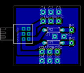
I put the resistors there because I have some sources that are pretty hot, and even with headphone amps at unity gain I don't get enough pot travel, so the resistor pads are there so I can lower the voltage to the amp/preamp.
If you don't need it I can make a version without them, or you can jumper them.
Cheers!
Russ
Attachments
Thanks Russ,
It looks like you dropped the drill size down one size to 0.7 mm and increased the pad to 1.9 mm.
Much appreciated. 😀
It looks like you dropped the drill size down one size to 0.7 mm and increased the pad to 1.9 mm.
Much appreciated. 😀
- Status
- Not open for further replies.
- Home
- Amplifiers
- Chip Amps
- A simple tiny PCb for those little alpha pots