Gaetan,
Try using a 10nF rather than 100nF across the baxandall diode in the quasi stage. I've found less is better here.
Nice circuit!
Hugh
Try using a 10nF rather than 100nF across the baxandall diode in the quasi stage. I've found less is better here.
Nice circuit!
Hugh
Gaetan,
Try using a 10nF rather than 100nF across the baxandall diode in the quasi stage. I've found less is better here.
Nice circuit!
Hugh
Hello Hugh
Yes, your right, I'll reduce it to 10nF, I've just found a 72's JLH amp and he use only 22nF, I should have look at it before.
It's a good amp but the noise floor are a bit high in the thd spectrum.
Thank
Bye
Gaetan
Attachments
post17 gave the source designers. Why has it taken so long to look up JLH?
Hello Andrew
I have, sinces years, accumulates hundred of schematics and texts about amps and electronics on my conputer hard disk and on cd's back-up. I was looking for a specific JLH amp and that was that 72's JLH amp, I did not remember the years and did not find it with Google, so I've need to look on my hard disk.
Thank
Bye
Gaetan
to use a transdiode .....
Hi Gaetan
In my thread: Quasi output: different configurations, there is an interesting concept to analyze, using a diode connected transistor as baxandall diode.
In post 17, Wimdehaan says; I noticed that a certain transistor configured as (baxandall) diode gave best measure. Here Mugen amplifier. What is your opinion?
Guillermo.
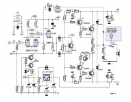

Here my proposal Quasi amplifier.
What are D1-D2and R17 for?
I think the +15v/-34v rails will benefit from some serious filtering but that should be easy enough, and all these simple quasi amps will need attention there I think.
D!,2?
In the event of output stage failure and rail voltage appears on the feedback line, D1,2 conduct and shunt excess voltage across C4, which is often some 10V rated part. Of course, with 38V rails and only 100uF, It would not be an issue for a 50V rated electrolytic or non-polarised type. It gets better, too with the addition of a reversed pair preventing excess reverse voltage which is not good for any electro. R17 remains a mystery. - Feedback scheme, perhaps? 😕
In the event of output stage failure and rail voltage appears on the feedback line, D1,2 conduct and shunt excess voltage across C4, which is often some 10V rated part. Of course, with 38V rails and only 100uF, It would not be an issue for a 50V rated electrolytic or non-polarised type. It gets better, too with the addition of a reversed pair preventing excess reverse voltage which is not good for any electro. R17 remains a mystery. - Feedback scheme, perhaps? 😕
Last edited:
Hello GEirin
Using a diode connected transistor as baxandall diode are a good ideas, that transistor will have a tempco quite similar to the output one.
R17 will also load the VAS and lower it's gain, but also the thd spectrum of your amp will have a more even harmonics, it may sound a bit more tube amp with that R17 in your amp.
Thank
Bye
Gaetan
the reduced gain, reduced output Z of the "VAS" are just about an even trade off if the VAS Q beta is linear over the added current swing required - but viewed only at that point
which leaves you "in the hole" in the bigger picture - because the reduced loop gain makes the input diff pair see larger error V, give larger distortion - and the trade off there is by the 2nd power of the input error V - so global loop gain is very powerful in linearizing the diff pair gm
the increased diff pair distortion is Odd order - I wouldn't want to predict "off the cuff" that R17 gives "even harmnonic structure"
Last edited:
the increased diff pair distortion is Odd order - I wouldn't want to predict "off the cuff" that R17 gives "even harmnonic structure"
Hello
In my push-pull lin topology amp simulations, loading the vas like R17 was giving more even order thd.
Thank
Bye
Gaetan
Hi G,
did you build this amplifier?
Is there a link?
Was it easy to tune in the component values?
did you build this amplifier?
Is there a link?
Was it easy to tune in the component values?
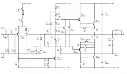
If you want to truly stick with 70's style design then you'll need to flip the input stage around. The LTP was always made up of PNP transistors so that the VAS could use an NPN driver. The bootstrap circuit is also common for that era of design, but shouldn't really be used in any modern amplifiers as a CCS is far superior 😛.
.......but shouldn't really be used in any modern amplifiers as a CCS is far superior 😛.
OOPS!!!
 There are some on this forum that will skin you alive for making such a statement.
Last edited:
I'm not trying to threadjack or anything, but the amp would be much better with a CCS than a bootstrap, it would also do better with Sziklai pairs on the output too.
Regarding a bootstrap, it's simple and does the job for most applications with a couple less components, even less if you use a two diodes as a reference, allowing you to add a CCS at the bottom of the LTP too with just one transistor, which is why vintage amps seem to use it so much, but because it becomes dramatically less effective at lower frequencies (the impedance is only half as much it would be without the bootstrap at the break frequency) thus allowing low frequencies to create surprisingly high levels of intermodulation distortion 🙁. This can be a real problem with even very little turntable rumble, if you are still using vinyl too, that is . Also, because it uses positive feedback, distortion is higher in general, as is noise. Best just to to use a CCS and cure the problem, not just eliminate the symptoms 🙂.
Regarding a bootstrap, it's simple and does the job for most applications with a couple less components, even less if you use a two diodes as a reference, allowing you to add a CCS at the bottom of the LTP too with just one transistor, which is why vintage amps seem to use it so much, but because it becomes dramatically less effective at lower frequencies (the impedance is only half as much it would be without the bootstrap at the break frequency) thus allowing low frequencies to create surprisingly high levels of intermodulation distortion 🙁. This can be a real problem with even very little turntable rumble, if you are still using vinyl too, that is
. Also, because it uses positive feedback, distortion is higher in general, as is noise. Best just to to use a CCS and cure the problem, not just eliminate the symptoms 🙂.Hi G,
did you build this amplifier?
Is there a link?
Was it easy to tune in the component values?
Hello Andrew
No, I did not have times to do more than Ltspice sim on my quasi amp and It seem that nobody have build my quasi amp.
I'm overwhelmed with the repairs of my old houses and also the modings of my last amp circuit.
I'm still working on a 14 simultaneous non-harmonically related sinewaves made by digital signals, it's for a more revealing IMD test and using a better sound card to look at the IMD spectrums of my amps under this 14 sines test. I've based that on the works of Nelson Pass about multitone IMD tests.
Bye
Gaétan
Last edited:
Certainly, if you expected the aim of the designer to simply be lowest distortion, that is part of the textbook approach to improving old designs......the amp would be much better with a CCS than a bootstrap, it would also do better with Sziklai pairs on the output too....
However, the quasi output stage (half CFP anyway) and a booststrap VAS are actually the essential sources of a desirable sound effect common to such retro designs, so you see it's really not a good idea to scrap them. 😉
- Status
- Not open for further replies.
- Home
- Amplifiers
- Solid State
- A simple quasi-complementary 50 watts amp