When you moved 0.47 from the emitter to collector of Q6, R19 drops to 18ohms, I think...
but that figure is no longer complimentary to Q5.
R18 differs from R21 because its effect isn't multipled by beta of MJL15003 (probably x50)
I think it better to leave R19 at 50, and restore the old 0.47 under Q6's emitter. That push
and pull emitter resistor magnification remains alike. Thats not to say get rid of the new
collector resistor, it too has a legitimate function. Its fine to have both...
39pF isn't all that uncommon.
Last edited:
When you moved 0.47 from the emitter to collector of Q6, R19 became 18ohms, I think...
I think it better to leave R19 at 50, and restore the 0.47 under Q6's emitter. That push
and pull emitter behaviors remain alike. Thats not to say get rid the new collector resistor.
Its fine to have both...
Hello
Some do put the emitor resistor on the collector side and some the other way, there is this Naim I've just found in my hard disk. So maby each ways do have pros and cons.
Thank
Bye
Gaetan
Attachments
To clarify:
Each does something important the other does not.
No need to choose, not a problem to have both.
Each does something important the other does not.
No need to choose, not a problem to have both.
I was mistaken, base of Q6 is fed pure current, not voltage.
Q6 base resistance is nothing compared to Q7 collector.
Emitter resistor R18 reflects nothing of significance here.
Put back the way Naim or Elvee had it...
May be a significant difference weather 50R spans across
emitter only, or spans across emitter in series with 0.47R?
i am not sure which is best, but any changes here have to
be reflected in the Baxandall.
Only now noticed you took out my 50R in series with the
Baxendall diode. That might be right answer considering
how the diode and base have same dynamic resistance.
They must, if we believe Shockley. And the 0.47 moved
out of the emitter equation.
I think you had it right at post #39.
Last edited:
kenpeter: When you moved 0.47 from the emitter to collector of Q6, R19 drops to 18ohms, I think...
but that figure is no longer complimentary to Q5.
R18 differs from R21 because its effect isn't multipled by beta of MJL15003 (probably x50)
I think it better to leave R19 at 50, and restore the old 0.47 under Q6's emitter. That push
and pull emitter resistor magnification remains alike. Thats not to say get rid of the new
collector resistor, it too has a legitimate function. Its fine to have both...
39pF isn't all that uncommon.
Hello
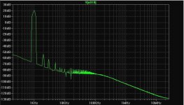
Here's my my fourth version (but #3) of my quasi amp with Kenpeter suggested mods, the schematic and the thd spectrum.
Thank
Bye
Gaetan
Attachments


Last edited:
Stop doing what I say, and listen to Elvee.
He steered you right while I was guessing in the dark.
I don't know why your spectrum looks better, its a sim.
He steered you right while I was guessing in the dark.
I don't know why your spectrum looks better, its a sim.
Stop doing what I say, and listen to Elvee.
He steered you right while I was guessing in the dark.
I don't know why your spectrum looks better, its a sim.
Hello
All ok, no harm done, I love simulation, you can test a circuit before doing real mods on the prototype.
Well, at first look the thd spectrum looks better, but there is more distortions.
Thank
Bye
Gaetan
In principle, C15 shouldn't be necessary.Hello
Here's my third version of my quasi amp with all Elvee suggested mods, the schematic and the thd spectrum.
Thank
Bye
Gaetan
Maybe a small value can have minor beneficial effects mimicking and fine-tuning the diffusion capacitance, but 0.47µ is probably too much.
Try 0, 22nF, 100nF for example.
And the diode should be a large, fast one, not a 1N4148.
gaetaan8888... you say you love simulating, well,
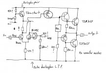
I remember a design many many years back in "Practical Wireless" that was a quasi design not unlike yours but it had one really unusual feature...
Q2 (looking at your circuit in post #45) would be a darlington and just single transistor for Q1
Is that easy for you to throw in your simulation to see what it does to the distortion spectrum on your circuit. Replace Q2 with a darlington like this.
This was just from memory of the original design.
No problem if not... just interested as it always sounded good to me at the time.
Attachments
In principle, C15 shouldn't be necessary.
Maybe a small value can have minor beneficial effects mimicking and fine-tuning the diffusion capacitance, but 0.47µ is probably too much.
Try 0, 22nF, 100nF for example.
And the diode should be a large, fast one, not a 1N4148.
Hello
I've replace the diode by a MBRS1100 and C15 by a 100nf.
Now the thd spectrum are better.
Thank
Bye
Gaetan
Attachments
Now the thd spectrum are better.
Gaetan
Hi!
getting better!
but the noise floor a bit too high... what makes THD relatively high...
gaetaan8888... you say you love simulating, well,
I remember a design many many years back in "Practical Wireless" that was a quasi design not unlike yours but it had one really unusual feature...
Q2 (looking at your circuit in post #45) would be a darlington and just single transistor for Q1
Is that easy for you to throw in your simulation to see what it does to the distortion spectrum on your circuit. Replace Q2 with a darlington like this.
This was just from memory of the original design.
No problem if not... just interested as it always sounded good to me at the time.
Hello Mooly
Not that I do lot a lot of simulations, but I'm very slow to build amps prototypes, so using simulation for preleminaries test are very usefull for me to get a quite close ideas about the amps, I look all voltages and currents and at the thd spectrum, not specially for the thd numbers but for the type of thd.
Thank
Bye
Gaetan
Hi!
getting better!
but the noise floor a bit too high... what makes THD relatively high...
Hello
Yes, noise floor a bit too high, maby it's my design but maby also because of my Spice directive in my simulation.
I've done this amp to be simple with easy to find parts for guy's who want to build a simple amp and try a quasi complementary type.
Thank
Bye
Gaétan
MBRS is a schottky, it isn't suitable. Use rather a MUR320 or 120.Hello
I've replace the diode by a MBRS1100 and C15 by a 100nf.
Now the thd spectrum are better.
Thank
Bye
Gaetan
Hello Mooly
Not that I do lot a lot of simulations, but I'm very slow to build amps prototypes.............
🙂
It's the other way around for me... really should try and get into using LTspice at least.
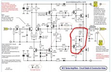
post45 is missing 0r47 in the collector of the lower BJT (Q6), it is there to kid on the driver emitter is seeing what the upper driver is seeing. It will then mimic the location of R21, mirror fashion.
Then fine tune the Shaw, Baxandall and JLH component values to find what matches best with the (approximate) simulation models.
Then you need to repeat the fine tuning with the real components in the real circuit.
I don't know how difficult or time consuming the real tuning will be.
Then fine tune the Shaw, Baxandall and JLH component values to find what matches best with the (approximate) simulation models.
Then you need to repeat the fine tuning with the real components in the real circuit.
I don't know how difficult or time consuming the real tuning will be.
Hello Andrew
Post45 schematic was just a try suggested by Kenpeter, I will not use
the post45 schematic.
The final schematic are this one.
Thank
Bye
Gaetan
Post45 schematic was just a try suggested by Kenpeter, I will not use
the post45 schematic.
The final schematic are this one.
Thank
Bye
Gaetan
Attachments

Last edited:
That's better, that is what I was trying to describe.
But, I still take issue with the value of R19
But, I still take issue with the value of R19
That's better, that is what I was trying to describe.
But, I still take issue with the value of R19
Hello Andrew
Reducing R19 to 30 ohm give a better thd spectrum.
Thank
Bye
Gaetan
Attachments
- Status
- Not open for further replies.
- Home
- Amplifiers
- Solid State
- A simple quasi-complementary 50 watts amp