Hi,
nearly there (R17 is far too high).
D1 is the Baxandall diode.
My math regarding R17 says:
26 ohms base to emitter resistance (Shockley)
another 23.5 Ohms for 4.7 Ohm emitter resistor
(0.47R times an approximate current gain of 50)
Looking at OnSemi gain curves at 1 Amp 25C
Don't know offhand the resistance of D1 1n4148?
I suppose you could subtract that and come up
with something slightly less than 49.5?
Lets calculate fwd resistance slope of D1:
from .7 volts to .8 volts I see 10ma to 20mA
Somewhere in the neighborhood of 10 Ohms?
But its curving logarythmically, and the value
drops as current goes up... Vishay's curve.
So maybe 39R for R17? On the lowish end.
I doubt 50 is gonna cause much a problem.
Due the curve you prolly want something
inbetween these extremes. Say 47. I think
you want the saturation end of diode curve
where resistance is lowest, not threshold
anyway. Shockley already separated curve
from 26R of his base, we need think same
way if this diode is gonna work.
"Far too high", no. Just about right.
Nitpick all day, diode is not the base of an
active transistor doing real work, just an
aproximation.
Last edited:
Hi Ken, thanks for taking the time to explain where you think 888 is getting his resistor value from.
I tend to disagree.
The 50r (R19) is there to mimic the 50r (R20) in the EF half.
The Diode is there to mimic the diode effect of the emitter of Q5.
R17 is there to mimic the effect of R21 in series with Q5.
C16 is there to mimic the capacitance of Q5.
Each of these components are trying to match the loading effects that the EF have on the upper driver.
Each of these components need to be optimised in value to suit the NPN devices used in the Quasi and the operating conditions that have been designed in.
I cannot be precise, because I have neither the skills, nor the equipment to measure/hear the effects of these mimicking components on the overall performance on the quasi stage. But even so, that 50r seems far too high.
I have given the reference Authors for each stage of the development and it is for 888 to read up if he desires.
Alternatively I may have misunderstood Baxandall and JLH and need to be re-educated.
Last edited:
My math regarding R17 says:
26 ohms base to emitter resistance (Shockley)
another 23.5 Ohms for 4.7 Ohm emitter resistor
(0.47R times an approximate current gain of 50)
Looking at OnSemi gain curves at 1 Amp 25C
Your 26 ohms isn't a base to emitter resistance, it's effectively a resistor in series with the emitter. It's value varies inversely with emitter current at 26/mA and is the same for any transistor, although some say 28 to 30 is more real world. I've never checked it myself, perhaps I should.
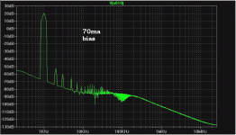
70mA bias was mentioned, so the intrinsic emitter resistance is 26/70 or about 0R37. Add that to the 0R47 R21 gives 0R84, multiply that by beta=50 and it's more like a 43R preferred value for R17 is the best match but if your beta is higher then your 50R may be spot on anyway.
Listen to a 70's designed Crimson quasi complementary amplifier. I have had 8 of the 1704s over the years. They are designed to sound good, rather than to be cheap. During this period they have been two to four times more expensive than the then current offerings from other manufacturers.
I don't think they are of the highest quality, but they did and do offer very good value for money.
Hello Andrew
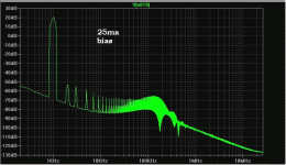
I do agree about those 70's designed Crimson, I still have one and it need only 25 ma. of bias and this amp sound very good.
Bye
Gaetan
Gaetan, you haven't commented yet on the 70 mA bias for your design. Would you like to say something about this particular current?
Hello Ian
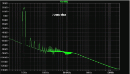
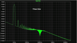
I've seen with LtSpice sim that there was a bit better thd spectrum at
70 ma. but there was not a big difference compared to 40 ma.
It's my first quasi complementary amp, so I may have not done an optimal design. But it was sounding very good.
Thank
Bye
Gaetan
I would have thought a larger D1 diode would simulate Q5 b/e better than a tiny 1N4148. Forward biased junction capacitances are huge for starters - I would estimate Q5 b/e as >0.1uF.
Yes, Sbrads, but if you parallel this tiny diode with a cap, as per JLH (around 22nF works very well), this makes up very nicely for the lack of forward capacitance.
But you do need a diode which can cope with max driver current, which could be as much as 50mA. 1N4148 with its 100mA peak might be a bit underrated anyway, so I'd go for a 1N4002 myself.
Hugh
But you do need a diode which can cope with max driver current, which could be as much as 50mA. 1N4148 with its 100mA peak might be a bit underrated anyway, so I'd go for a 1N4002 myself.
Hugh
I would have thought a larger D1 diode would simulate Q5 b/e better than a tiny 1N4148. Forward biased junction capacitances are huge for starters - I would estimate Q5 b/e as >0.1uF.
Seems I never properly learned Shockley. Make an idiot of myself.
Dumb luck I would figure a right resistor with an entirely wrong formula...
But I've re-studied up on Shockley, and his diode law fresh on my mind.
DynamicResistance = 26mV / BiasCurrent
Anyways, current in 1N4148 diode is 50 times less than the power Emitter
due to beta. Therefore 1n4148 dynamic resistance is 50 times higher than
said Emitter, but Base also scales up Emitter resistance by this same beta...
So dynamic resistance slopes auto-magically match, size matters not???
Go figure... Seems we only need scale up the static resistances to match.
Capacitance match is another story, diode size might yet be relevant?
Last edited:
Yes, Sbrads, but if you parallel this tiny diode with a cap, as per JLH (around 22nF works very well), this makes up very nicely for the lack of forward capacitance.
But you do need a diode which can cope with max driver current, which could be as much as 50mA. 1N4148 with its 100mA peak might be a bit underrated anyway, so I'd go for a 1N4002 myself.
Hugh
Hello Hugh
So a cap across D1 are a good ideas ? (as I show in my post #14)
I can replace the 1N4148 by a 1N4002 in my schematic.
Thank
Bye
Gaetan
Hello
I've decided to read a bit about the diode+resistor that you suggested me.
Gaetan
The diode is called a baxandall diode.
It increase the gain of the lower driver. This is good but it also increases the possibility of oscillatiion on the output, hence making c15 bigger. That was certainly my experience on one of my designs. I got up to 100pf for c15 to stop osc.
The diode is called a baxandall diode.
It increase the gain of the lower driver. This is good but it also increases the possibility of oscillatiion on the output, hence making c15 bigger. That was certainly my experience on one of my designs. I got up to 100pf for c15 to stop osc.
Hello Nigel
Would a 100pf cap for C15 could slow-down a bit the output section of the amp ?
Thank
Bye
Gaetan
Hello Nigel
Would a 100pf cap for C15 could slow-down a bit the output section of the amp ?
Thank
Bye
Gaetan
My advice would be to leave c15 at 15pf for now.
Get the amp running and check for oscillation on the output. If there sint any then c15 is fine. If there is then increase c15 slowly until the oscillation goes.
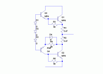
The placement of R22 is irrational and ineffective: it only contributes to waste power, but does nothing for thermal stability.
Here is a better way to use it.
D4 has to be a large epitaxial (fast) diode, to optimally match the B-E junction of Q1 working in transistor mode.
This arrangement should give the lowest even harmonic level.
Here is a better way to use it.
D4 has to be a large epitaxial (fast) diode, to optimally match the B-E junction of Q1 working in transistor mode.
This arrangement should give the lowest even harmonic level.
Attachments
Bias v HD
Thanks Gaetan, it sure seems improved with increased bias, just as you say. Perhaps you have also run lower and higher
fundamental frequency spectra to check frequency dependence. (Just a small suspicion - I'm like that!) 😉
That looks like a great result - improves lower harmonics distribution and damps some nasty high harmonics too... ....Here the thd spectrum, with LtSpice, for 25ma bias, 40ma bias, 70ma bias...
Thanks Gaetan, it sure seems improved with increased bias, just as you say. Perhaps you have also run lower and higher
fundamental frequency spectra to check frequency dependence. (Just a small suspicion - I'm like that!) 😉
Hello
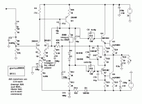
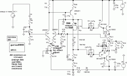
Here's my first version of my quasi amp with minor mods, the schematic and the thd spectrum.
Thank
Bye
Gaetan
Here's my first version of my quasi amp with minor mods, the schematic and the thd spectrum.
Thank
Bye
Gaetan
Attachments
Last edited:
C2 is 37pf, I didnt know you could get a 37pf, its usually 33pf or 47pf
Hello Nigel
I use to take apart all my burnt or defect gears that I can't repair, few are 50 years old with odd parts from the twilight zone, I think this cap come from an old 1950 british tube scope.
But your right I should put standard value on my schematic.
Bye
Gaetan
- Status
- Not open for further replies.
- Home
- Amplifiers
- Solid State
- A simple quasi-complementary 50 watts amp
