Still there is high current at low volume.
Your comment gives me an idea, don't know how it would work in real life, but how about putting a timer on the program so that when the shunt resistor has been above a given current, say 4~5 ma, the device self-mutes after 1 hour or two hours? That way, you can listen to music at a low level but if you forget and walk away with the LDRs set that way, the one-hour limit will protect the LDRs from many hours or days of high current?
Maybe that would practically eliminate LDR aging? I think I'm going to incorporate that into my design . . .
Made clearance holes in pcb - no solid connection
usb dac is all solid state, no valves - no idea why this is so sensitive but found similar things in some other dac's, not just the Ayre.
The manufactured low mass shock mounts are both expensive and hard to find in small quantities, unfortunately, for silicon, sorbothane, etc - ended up making some up using insert nuts, thread and silicon rubber - those Lords instrument mounts are not cheap.
Oenbeck, good idea about reducing led current when muted - might try to 'hitch' the power amp sensor turn-off system to the volume control mute relay also or possibly, a method of sensing when no power output from amp for 'x' minutes and then 'auto-mute' the vol control (like the way some preamps have an separate 'enable' voltage that controls the amp's output relays, but in reverse)
This way is a bit cumbersome but it shifts any 'no music playing' sensing method out of the small signal path.
Could also add an indicator to show when unit's 'muted' - a 'flashing' led to attract attention/annoy?!
I remember George saying that he's seen no indication of led/ldr aging and his units have been in use for some years now - how significant is this 'aging problem'?
I remember George saying that he's seen no indication of led/ldr aging and his units have been in use for some years now - how significant is this 'aging problem'?
Correct, my prototype now over 8 years old and has been powered for 24/7 has the same perfect balance and gain curve it had when first built, and has never been had to be re-calibrated.
The only time I have seen a quad set of NSL32SR2S which I use damaged or weakened, is when they have been moded and used at over 20mA or when the input signal was extreme (and maybe with output shorted) and way over normal source level output voltage, or hammered by test bench audio generators that were push up way too high in level.
There have been many hundreds of Lightspeed Attenuator now manufactured, I have never seen one come back for repairs that have "aged" through normal use.
Only a couple that have been seriously abused by one of the above conditions, and this then is only fixed by a replacement repair of the quad matched set of NSL32SR2S.
Cheers George
Hi, I had build with very low current 1.2 ma, the resistance are around 140 to 200 ohm. I select those below 170 ohm used for shunt.
I control the series LDR > 600Kr when the pot at minimum (7 O'clock)
when the pot rotated to 9 O'clock the resistance reduce to >100Kr.
When the pot at 12 O'clock the resistance reduce to 15kr, around 2 Kr at 3 O'clock, less than 200 Ohm at 5 O'clock position.
The shunt LDR resistance vary from around 150 Ohm(7 O'clock) to 20 Kr(5 o'clock). At 9 O'clock is about 500 Ohm,12 O'clock around 6 Kr, around 16 Kr at 3 O'clock.
With 1.2 ma low current those LDR is much stable than 10 to 20 ma range, it can stay at low volume position for ever, but it need
temperature compensation otherwise the high resistance range will drift a lot.
I vary the voltage by the volume pot from around 1.6V to 2.9V, then regulate
the voltage around 1.4V - 1.7V to the LDS.
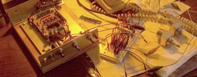
Looks like you had fun?? and would have had trouble, looking at the amount of trimpots you needed for this balanced one.
As I've said many times I will never do XLR, to do an XLR Lightspeed is more than exponentially harder to do, even impossible.
And to do any form of auto calibration is also fought with problems, as the active auto calibration circuit has to be attached the the signal output.
And whatever type of auto calibration circuits we used with all our prototypes, it had a detrimental effect on sound quality compared to doing it the hard way and just matching up quad sets.
Cheers George
Attachments
I'm working on the IR controller software and have encountered an interesting issue. All remotes have volume up/down buttons and a mute button. Very few have "balance" controls as a primary option. I would like to have a motorized balance control. What to do?
I'm working with the Sony SIRC code so that anyone will be able to take a universal remote or a Sony remote and run my IR board, and the obvious solution conflicts with the standard SIRC control codes. By "obvious solution" I mean taking over the four-way rocker switch on the remote to run volume up/down and balance left right. Makes sense, right?
The problem is that in doing that I'd be modifying the Sony standard so if you programmed a universal remote for Sony you'd wind up with conflicts in what button does what. Even worse, if you used my IR/LDR setup in a system with a Sony TV or receiver or DVD or whatever, all kinds of screwy things could go wrong.
I think I'm going to solve this by putting a jumper on the IR board (it's getting crowded!).
One selection will be strict Sony codes so that a Sony remote or a universal remote programmed for Sony will work exactly as it should. If you can program your universal remote with a Sony receiver/preamp code, the balance controls become available if you've got the buttons to do it. Sony TVs don't seem to have balance codes included.
The other selection will be simpler and work with any Sony TV remote code -- as long as you don't try to use it in the presence of other Sony components. This selection will add the four way rocker to the normal volume up/down and mute buttons so you can have balance control at your fingertips.
Anybody have any thoughts or suggestions on the subject?
Last edited:
The final piece has come together. Have now breadboarded the IR receiver and it works perfectly. Since the breadboard wiring is per the PCB design I anticipate no problems from here out.
I was running the pot motors off the LDR board 5V regulator so, after subtracting the 1.4V lost in the H-bridge chip, the 4.5V motors were underpowered and didn't run very fast, but operated correctly.
I will now order some boards and see how the real thing works. The IR PCB has a 6V regulator dedicated to the motors so they'll run well in the final configuration.
l think I'll go pull the cork on a beverage and relax for a while. 😀
Attachments
what happens when ywo Sony buttons are held down together?
Or when one button is held and another is clicked - repeatedly?
Or when one button is held and another is clicked - repeatedly?
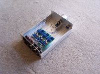
Here is the (un)finished IR board -- works a treat, but I've already decided on final-final changes.
I've already decided to convert the pins to screw terminals to match the front side. That way if someone wants to use it stand-alone to put IR in their own amp, the connections will be easy. Alternatively, if used in conjunction with the LDR board then all that's needed is a row of header pins inserted into each side to connect the screw terminals to the screw terminals on the main board to make a rigid connection.
Also changing back to 2.5 inches wide to allow space for standoff holes on each side of the board to allow separated installation or standalone use.
Also moving the "DC IN" off the IR board to the side of the main board and taking power from there for the regulator on this board. That will reduce one of the screw terminals on the front from six to four connections and eliminate the diode which duplicates a diode on the main board.
I'm making the main board 2.5 inches instead of 2.3 inches. First, I don't see the benefit of squeezing those last .2 inches and, second, it will match the size of the IR board. And I suppose, third, down the line if I want to add something I hopefully won't have to change the size of the board so it will continue to match the IR board.
Attachments

Last edited:
Very neatly done - can still mount on it's side if short of room if terminals used - useful option - suggest you keep the diode as extra protection, maybe stand it up vertical.
Any possibility of small SMD diode(s) to indicate when the motors are activated (and hopefully the volume changes!) - a sort of 'function check' indicator?
Can use those plastic standoffs or even the self adhesive ones - they work really well if the surfaces are clean and seem to stay glued okay for years - can make/cut some round/rectangular supports from that automotive double sided flexible/cushion tape for vehicle bumper strips/ornaments/etc - 'sticks like mad' and useful anti-vibration.
Your project is nearly finished - looking forward to the field testing ....
Very neatly done - can still mount on it's side if short of room if terminals used - useful option - suggest you keep the diode as extra protection, maybe stand it up vertical.
Any possibility of small SMD diode(s) to indicate when the motors are activated (and hopefully the volume changes!) - a sort of 'function check' indicator?
Can use those plastic standoffs or even the self adhesive ones - they work really well if the surfaces are clean and seem to stay glued okay for years - can make/cut some round/rectangular supports from that automotive double sided flexible/cushion tape for vehicle bumper strips/ornaments/etc - 'sticks like mad' and useful anti-vibration.
Your project is nearly finished - looking forward to the field testing ....
James, your post is timely, I'm wondering how to go forward from here and how to beta test is on my mind.
But first regarding the SMD diodes, there is no room, I struggled to make it all fit as it is. The problem is the crosshatch of traces across most of the middle of the board. I tried to find alternative placement of the components, but nothing else seems to work. Also, I like to keep my traces pretty big -- a result of having ruined lots of traces with a soldering iron in my earlier days. Off the board you could parallel the motor leads and have different colors for different directions. The voltage will be about 4.5V with different polarity depending on which direction the motor is running.
The power diode is no longer necessary because in my next "final" version the IR board takes power from the downstream side of the input diode of the LDR board.
Now, regarding the project as a whole, the hardware really is finished for now, although the "production" version of the boards will have some final changes.
The software seems mostly finished, I just need to make a portion of the calibration software a tad more conservative to take into account the variability of the LDRs. The other day I re-examined my small stash and found that quite a few would go to 35 ohms at 10 ma so I'm going to shoot for 35 ohms as the "standard" shunt minimum resistance. The series resistance will wind up somewhere between 100 ohms and 50 ohms and it won't make a hill of beans difference, and that's where the less stellar specimens will get used.
I went through the calibration and playback modules today and found a way to get a more accurate calibration in less time so it was an afternoon well spent. The playback really is finished, I can't think of anything left to do except maybe a final cleanup inspection of the entire program.
One question: If I understand correctly, the two pot values that I should be working toward are 10K and 50K for solid-state and tube, is that right? Or are there other values that are commonly used? I could go 100K but that would be at the upper limit of reliable control for now.
I must confess that I've been so involved in getting the technology right that i have never actually listened to my creation yet. I've got the RCA jacks in hand, I need to drill some holes in my test jig and set them up. Actually, I need a new test jig -- the old one is too short front-to-back to accommodate comfortably the LDR board and the IR control board. I'm really looking forward to the thrill of controlling my creation from across the room! 😀 That's the obvious next step.
I'd like to do some log pot curve testing. Others have done distortion testing (about which I have a question) and the qualities of LDRs are well known. The only real question I have is how close to logarithmic is my virtual pot going to turn out to be? I need to figure out how to do that test.
After that, what next? I guess beta testing. I'm leaving on a two-week trip in a few days, I'll ponder this while I'm away.
Yes, it's got quite busy on the board but it does seem to still make a logical sense so I'd just ignore my 'natterings' - perhaps, later on there might be some other upgrades and perhaps then ....
There was a strange idea about the donuts awhile ago that had very little copper around the hole but small fingers leading to an outer hole - makes for quick soldering but a nightmare for any repeat components -
Curiously, one of my early ideas was to just leave the donuts on the pcb and hard wire the components (like a point-point assembly) - I still do some assemblies this way - my F5 amp definitely sounds better this way especially with better copper wiring instead of basic copper tracking.
I wouldn't get too concerned about trying to 'eke out' the least remaining Ohm from the ldrs - in actual practice, there's not much difference between a 35R ldr and a 100R ldr - I've always been a bit puzzled why the idea of absolutely minimum resistance values seems to attract such enormous attention - with Uriah's you get the option of setting your own minimum resistance and I've tried mine at both 40 R and 100 R and there's just no way that I can hear, or measure any difference at all, including headphone testing - IMO, it 'just ain't worth a worry'
The basic values these days seem to be 10kR, 20kR, 50kR and 100kR - if it's just a matter of programming and initial ldr selection, you might be able to offer all these values
As for accurate log curves - for audio use, it probably isn't all that critical provided there's a good relationship between the 2 channels - you do see the stepped attenuators advertising about +/- 0.25dB accuracy and apart from the L <-> R balance, not much point - we don't listen via knob setting numbers
However, on the professional side, it's a whole lot different as they need to know that the device is going to maintain it's set values after repeated adjustments and the values are going to be always accurate - there's big bucks in this sort of quality.
Have a good trip - I recon you've earned a break.
Lots of interesting points here --
1. Donuts with fingers -- are you talking about thermal pads which are designed to make soldering easier because they prevent the surrounding copper from wicking up the heat? And they cause a change in sound? Two weeks ago, I would have said unbelievable, but last week I went to a demonstration of what cables can do to sound. Not just speaker cables, but all cables including power cables and USB cables. Before the demo I knew it was impossible but during the demonstration I personally heard non-trivial improvements in sound when cables were swapped out for higher quality. The system consisted of full-size Magnepan speakers, tube-based amp blocks that I couldn't begin to lift without help, and outboard DACs and vibration-reducing pads for everything and HD level source. If a USB cable can affect the sound of the digital signal crossing it, I believe that a solder pad can affect the sound crossing it, too. But when I think of the total cost of a sound system that includes $14,000 speaker cables my eyes glaze over. So, I think that in my design the solder pads probably are not going to be audible. And there are no thermal pads in the signal path, only the LDR control circuit. 🙂
Regarding the minimum resistance of the pot, you may be right about that, but consider:
1. I need a bottom resistance to program into the code that runs the control, and it has to be consistent (not customizable for individual LDRs) so I need to think about it and reach a conclusion.
2. For sensitive systems with a lot of gain, perhaps every dB of attenuation will be valuable.
3. I can hit that 35 ohms with 10 milliamps of current which is one-half of the manufacturer-claimed safe level of 20 ma. Now, is 10 ma too much for long term stability of the minimum resistance? I don't know, I don't think so (and hope not). Does anyone know for sure? If it turns out that 10 ma is a little too much, there is always the option to recalibrate and if there is some degradation the only practical effect should be a raising of the ohmic floor from 35 upwards to some other value at the same 10 ma.
4. Eventually, any pot value between 10K and 100K will be possible, I was wondering if the "industry standard" included more than 10K and 50K. You've answered my question.
5. Regarding the accuracy of the log curve versus accuracy of the channel matching, in this system they go together. If the channel matching is tight, then the same systemic precision will apply to the log curve (assuming my math is correct, and that's always questionable with me).
I'm hoping that whatever the inaccuracies are, they will be inaudible and/or immaterial. One of my hopes for this system is that it will be a good combination of precision and cost-effectiveness and small size so that if someone wants multiple channels for professional or personal use, it will be possible to use it that way. We shall see, it hasn't even reached alpha testing yet . . .
So, I have another question: does anyone have a working method that I could adapt to permit me to measure the predicted vs actual attenuation of my board? Something that would control the input level across the range from minimum to maximum attenuation and correlate it with the output attenuation with the ability to graph the result? I'm wondering if MakerPlot is my solution, or what else is out there.
I wouldn't get too concerned about trying to 'eke out' the least remaining Ohm from the ldrs - in actual practice, there's not much difference between a 35R ldr and a 100R ldr - I've always been a bit puzzled why the idea of absolutely minimum resistance values seems to attract such enormous attention - with Uriah's you get the option of setting your own minimum resistance and I've tried mine at both 40 R and 100 R and there's just no way that I can hear, or measure any difference at all, including headphone testing - IMO, it 'just ain't worth a worry'
James, surely there is a very significant difference in how low you can turn the volume when comparing 100R vs 40R as the bottom of a 10K attenuator? The difference between 50 ohms and 35 ohms shunt resistor on a 10K pot seems to be about 2.5 dB, between 100R and 35R is 9.5 dB which I think is a big difference in capability. Marketing wise, offering the maximum attenuation possible is desirable, but how useful is 2.5 dB? I'm not sure. Opinions, anyone?
Oh, perfect. Here I sit in Wisconsin, USA, and so far potential beta testers are in Australia, Catalonia, and Pretoria. What's wrong with this picture??!! 😱 LOL!
- Status
- Not open for further replies.
- Home
- Source & Line
- Analog Line Level
- A precision LED/LDR-based Attenuator