I thought that the ldr input/outputs are on the green terminal blocks. It would be nice to have the audio circuit all soldered, though.
One way would be to mount the RCAs on the board.
Yes, the LDR audio path is connected via terminal blocks. My point was that a non-solder approach to connecting the LDRs to the circuit card would introduce yet another unsoldered connection.
You could put RCA jacks on the board but everyone seems to have their own idea of what an RCA jack should be in terms of configuration, quality, materials, etc. Better to leave that to the builder.
If you want to go all-soldered, then it would be easy to solder the i/o wires to the pads under the terminal blocks, but that would be a pain in the neck when you wanted to recalibrate your LDRs and I would not recommend that.
On the other question -- you're talking about a pot with the opposite slope of a conventional volume control to be used in a tone control section? Where can I see the complete circuit?
Ah, that's found in the "High End Tone Control" thread, post 36 - ThorstenL - it's very simple and I've found that the OPA627s can give pretty good results if care taken with power supply (as per the same post, can use other gain stages also) and some of the resistors are low enough value that I can make some of these here myself with the Manganin wire so keeping the cost down to a reasonable level - have plenty of good styrene caps to suit, etc do it's just those difficult pots that are the problem here.
I had a brief look at Rod Elliot's esp site last night to see if there's a way to do a 'fake anti log pot' and will need to have another look - I think it's quite possible but not 'clued up' enough yet ....
There's another quite attractive circuit for tone controls setup by a Michael Bean that's rather well thought out in the "Usable Tone Controls" post #45 with a couple of ICs in line but these also can probably be substituted altho the output impedances make this not so easy - the stepped attenuators provide a way around the volume pot problems and maybe this is another area where the benefits of the ldr pots can be well utilised
Don't know if either circuits will be at all popular and mightn't be worth the trouble to develop the 'curves' for a possible 'kit' but if something like this can be relatively easily designed, then quite a few other 'impossible to find' pots may also be offered, particularly if the cost is reasonable.
For anyone reading this 'stuff', the quality of the resistors in tone controls, particularly the popular Baxandall ones, are directly tied to 'sound quality' and the control pots are the biggest problem of all - stepped switches are great but only if 'good' or excellent resistors are used - it's generally a balance between cost and benefits, as usual.
Back in the days of analogue mixing desks, the top desks (Harrison, Neve, etc) had very high quality slide switches of horrendous cost and even the 'man himself' wasn't allowed to take a fluid drink or cigarette anywhere near these desks - the cost of getting them cleaned was even a crazy price - not available anymore but I think with this particular version of the LightSpeed vol control, it may once again be possible to achieve that wonderful 'sound' that was created by those old analogue desks with the benefits of the modern digital systems - (maybe 'smoke dreams' too, I guess ...)
sorry -
very high quality slide switches of horrendous cost
should read
very high quality slide volume pots
very high quality slide switches of horrendous cost
should read
very high quality slide volume pots
For anyone reading this 'stuff', the quality of the resistors in tone controls, particularly the popular Baxandall ones, are directly tied to 'sound quality' and the control pots are the biggest problem of all - stepped switches are great but only if 'good' or excellent resistors are used - it's generally a balance between cost and benefits, as usual.
Back in the days of analogue mixing desks, the top desks (Harrison, Neve, etc) had very high quality slide switches of horrendous cost and even the 'man himself' wasn't allowed to take a fluid drink or cigarette anywhere near these desks - the cost of getting them cleaned was even a crazy price - not available anymore but I think with this particular version of the LightSpeed vol control, it may once again be possible to achieve that wonderful 'sound' that was created by those old analogue desks with the benefits of the modern digital systems - (maybe 'smoke dreams' too, I guess ...)
James, I went looking (had to use Google, the thread has been renamed) and I understand the principle. But some of those controls used 500K pots -- not sure how practical that would be with LDRs. I've had LDRs under control at 500K once or twice in test jigs but the resistance wandered a lot up there, and occasionally the LDR would cross some kind of threshold and suddenly drop out entirely. I guess the LED is operating right at the absolute limit of control, and the control if very unreliable at that level.
I wonder if we're thinking the same thing about slide controls? The reason that I made this board jumper selectable Stereo or Dual Mono was to enable multi-channel operation -- as in a multi-channel mixing board or 7.1 surround or whatever. I think the accuracy of the pot under PIC control will make it quite easy to have a ganged pot of a virtually infinite number of "wafers" or to create a mixing board of many channels. A variety of things are possible, for example put the slider controls in one box in a console at room temperature and place the LDR cards in an entirely separate refrigerated box down on the floor to keep a hundred channels dead steady within a climate-controlled box. Because no signal travels between the pot and the board, sound will not be degraded by the distance between slider and LDR board.
I had an 'aha' moment this afternoon, and I think I've figured out where I want to go next. There is an issue with using LDRs that a variety of people have expressed dissatisfaction with and I think I can deliver the solution. James, I think it's going to be a while before I get around to tone controls, sorry!
I've got parts on order for the IR remote prototype. My solution should work with any remote control that uses the Sony SIRC standard, and that includes universal remotes so there should be no problem integrating this LDR assembly into existing remote-controlled audio systems.
Yes, high impedance pots are always a PIA
Many of the higher quality hifi tone controls, shelving networks, etc use the more normal range about the 10k/20kR - that's one of the things that attracted me to these particular circuits,
Anyway, antilog pot design can't really be at all a high priority but I think an alternative 10kR linear pot could find quite a few customers and can possibly derive a reasonable antilog pot from that via that 'fake-law' idea - I will ask Rod (Elliot - esp) and see ...
I also think that the main controlling pot can be quite a distance away from the active circuit - might have some problems with stray line capacitances, etc but essentially can't see any reason why this can't be expanded on - a fairly simple extension
In fact, because of the calibration system and tight control, there's probably a lot of areas that would require a precision impedance(s) and maybe not a volume control at all, where a digital version just won't do.
I wonder if we're thinking the same thing about slide controls? The reason that I made this board jumper selectable Stereo or Dual Mono was to enable multi-channel operation -- as in a multi-channel mixing board or 7.1 surround or whatever. I think the accuracy of the pot under PIC control will make it quite easy to have a ganged pot of a virtually infinite number of "wafers" or to create a mixing board of many channels. A variety of things are possible, for example put the slider controls in one box in a console at room temperature and place the LDR cards in an entirely separate refrigerated box down on the floor to keep a hundred channels dead steady within a climate-controlled box. Because no signal travels between the pot and the board, sound will not be degraded by the distance between slider and LDR board.
By the way, using my design, it is dead easy to have a "master" volume control to control all channels at once plus separate individual controls for each channel, and master controls and channel controls in any combination, mixed and matched to aggregate any set of sub-channels under a given master control, and it can be done with simple DC switches. That would make a console pretty flexible, I think? And of course, the 10K linear pots I use could be replaced by manual or motorized slider controls for any level of sophistication.
Does the attenuator come ON at the same volume at start up?
Is this start up volume presettable?
My car radio does this.
If I switch off when it's high it remembers the preset and comes on quietly next day.
If my last journey was set to quieter than preset. It temporarily remembers that lower setting and comes on at this very low setting.
Is this start up volume presettable?
My car radio does this.
If I switch off when it's high it remembers the preset and comes on quietly next day.
If my last journey was set to quieter than preset. It temporarily remembers that lower setting and comes on at this very low setting.
The other day I ordered new boards and enough parts to populate them. While I'm waiting I fooled around with the board layout to eliminate most empty space and was able to reduce the total size of the board to 2.2 inches by 3.3 inches, and as I look at it again I see that I can cut another .1 from that 2.2 inch dimension.
I looked at those dimensions on a ruler, and was surprised by how small a board will hold a good power supply, a PIC, four LDRs and drive components and a bunch of screw terminals for connections not to mention a row of holes used only to store the calibration board when it's not in use. And that's with through-hole components. With surface mount and taking advantage of an existing +5 supply in a preamp, I could build a board small enough to fit in -- to retrofit with LDR controls -- practically any preamp out there . . .
I looked at those dimensions on a ruler, and was surprised by how small a board will hold a good power supply, a PIC, four LDRs and drive components and a bunch of screw terminals for connections not to mention a row of holes used only to store the calibration board when it's not in use. And that's with through-hole components. With surface mount and taking advantage of an existing +5 supply in a preamp, I could build a board small enough to fit in -- to retrofit with LDR controls -- practically any preamp out there . . .
Last edited:
Final dimensions for this iteration:
Main board: 2.3" x 3.3"
IR Remote board: 2.3" x 1.25"
The limiting factor on the width (2.3") is the IR board, it just won't get any better than that. Still, the package of precision LDR control plus motorized pot and mute remote capability is 2.3" x 4.55" total, which should be small enough.
The remote can be used stand-alone for an existing installation or alternative preamp, or screwed directly into the main board input terminals.
I know that this doesn't make much difference with your testing & control system but with many of my 'led groups' (the 4 leds) I wrapped a couple of layers of Aluminium foils around them (ensured no contact with wires) and coated all this in wax to keep them at the same/similar temp - a follow on fron George's original idea - possibly a waste of time but .....
Nearly finished your design now - sound quality testing next ...?
Nearly finished your design now - sound quality testing next ...?
I know that this doesn't make much difference with your testing & control system but with many of my 'led groups' (the 4 leds) I wrapped a couple of layers of Aluminium foils around them (ensured no contact with wires) and coated all this in wax to keep them at the same/similar temp - a follow on fron George's original idea - possibly a waste of time but .....
Nearly finished your design now - sound quality testing next ...?
I have all the components now, and my newly minted main board arrives tomorrow. I'll wait on the IR board until I've confirmed the LDR board, instead I'll breadboard the IR circuit first. I had to do some fancy trace squeezing to get it down so the width of the IR board matches the LDR board.
You raise a good question about the temperature effect, and I've thought about it off-and-on all the time I've been fiddling with LDRs. One thing about LDRs -- we all know, or have heard, that they sound great. But there's darn little hard information available on their operation.
I can remember maybe four years ago now, I tested a bunch of LDRs and found that at the currents we were interested in they were not 2.5V devices, they were all in the range of 2.0~2.2 volts, and if you had a 5V source and inserted current limiting safety resistors assuming the LDR needed 2.5 volts, the resistance values you came up with were not adequate to limit the current properly. At that point I'd come to the party late, but no one had previously bothered to do the testing. Also, I can remember that there was no reaction from others, and no change to the advice/design parameters within the simple circuit group.
Same thing with temperature -- we all assume that temperature affects LDR performance and I've seen it happen myself and know it's true, but no one has done any testing to determine just how much an LDR changes with a, say, 10F temperature change, and while unproven, I'm guessing that the effect will be greater at the low current end of the spectrum. Because of the lack of hard data, I'm unwilling to implement any temperature control actions like you describe unless/until I am able to do some accurate testing of temperature versus resistance behavior. If, for instance, the effect is only significant at the low current high resistance end of the spectrum, it probably won't make much difference to real-life attenuation since the low value R has greater impact. It's one of the things that's on my agenda to check on.
Also, regardless of sensitivity, if the LDRs are on a board contained in an enclosed space, I can't see the temperature varying more than a few degrees from one end of the stack to the other end, and in that circumstance I wonder if they really need to be wrapped together?
Last edited:
I think both Uriah and George did some work on the resistance change that small temperature differences produced between the ldrs but this was some time ago - this was mostly geared towards channel balance and such rather than the specific resistance changes with temperature -
I don't remember anyone posting any specific measurements for this but I would imagine they would be more sensitive to change at the low current, higher impedance area
What makes these things a bit hard to 'get a handle on' is that as the current thru the led changes (< 10uA - 10mA for volume requirement changes, for example) the device itself is going change it's temp quite a bit (neatly dodged anything specific there, did you notice!) and hence it's ldrs are going to change their resistance in response - not much can be done about this, I think.
But, by mechanically and thermally connecting them all together, the hotter harder working ones will tend to heat the cooler ones and attempt to establish a temperature balance between them all to reduce the temp differences between any of them
It just seemed to me that if I could keep them as close as possible to a similar temp, then their performance would be more consistent
I don't think this would matter much in your system as you're using an active control technique to maintain impedance where the wholly passive method will have resistance variations that are dependent on device temp.
I don't know if there is a difference in the sound of the devices when any of them are hot or cold in actual practice but, like most things in audio, when things are well and truly warmed up, they generally do sound better.
Instead of the usual voltage control, I prefer a precise current control of LDRs. Matching them beforehand provides a greater consistency that hopefully allows them to stay more closely matched with minor temperature variations. The power we're talking about here is about 0.1 to 0.2 mW (at least in my testing and assuming 50% volume setting, counting both the LED current and a worst-case 2v p-p sine wave through the resistance element), so I don't expect much heating. I think George potted his Lightspeeds to try to prevent reverse engineering rather than to ensure temperature consistency.
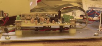
Here is an image of my latest prototype with James Hill's brilliant idea for calibration board storage implemented on the far side of the main board. The pins that connect the board to the LDR board fit into a set of holes that match the pattern.
Thank you, James, it's really useful!
Also note the location of the LM317T regulator -- under the board. The board is diminutive and the ugly 317 towers over it when placed on top. It only gets warm to the touch for about a minute during calibration and does not produce any heat at all during normal operation. It's perfectly safe underneath there. Final production will sport the plastic enclosed version of it -- pricier but no need for insulation of any kind, even under the board.
I tried to save some money by ordering a board without soldermask. Never again! Solder runs everywhere, you can't tell when you've applied enough. It works OK, but I don't like the look -- amateurish!
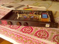
I came across a VTL TL-2 preamp in a Goodwill store (thrift shop) the other day. It is a vacuum tube preamp that was high-end in the early 1990s. (There's currently one for sale on eBay for $1988 plus $85 shipping from Hong Kong.) You wouldn't believe what I paid for mine. (Literally, almost nothing! 😀)
Anyway, it works perfectly and there is a lot of open space in it. I think it'll be the first real-world implementation of my IR remote-controlled volume & balance & mute circuit. It won't be totally passive in the end and the technology in this amp has long ago passed into history, but it sure does demonstrate this circuit's ability to replace those controls in an existing preamp.
Thank you, James, it's really useful!
Also note the location of the LM317T regulator -- under the board. The board is diminutive and the ugly 317 towers over it when placed on top. It only gets warm to the touch for about a minute during calibration and does not produce any heat at all during normal operation. It's perfectly safe underneath there. Final production will sport the plastic enclosed version of it -- pricier but no need for insulation of any kind, even under the board.
I tried to save some money by ordering a board without soldermask. Never again! Solder runs everywhere, you can't tell when you've applied enough. It works OK, but I don't like the look -- amateurish!
I came across a VTL TL-2 preamp in a Goodwill store (thrift shop) the other day. It is a vacuum tube preamp that was high-end in the early 1990s. (There's currently one for sale on eBay for $1988 plus $85 shipping from Hong Kong.) You wouldn't believe what I paid for mine. (Literally, almost nothing! 😀)
Anyway, it works perfectly and there is a lot of open space in it. I think it'll be the first real-world implementation of my IR remote-controlled volume & balance & mute circuit. It won't be totally passive in the end and the technology in this amp has long ago passed into history, but it sure does demonstrate this circuit's ability to replace those controls in an existing preamp.
Attachments
Instead of the usual voltage control, I prefer a precise current control of LDRs. Matching them beforehand provides a greater consistency that hopefully allows them to stay more closely matched with minor temperature variations. The power we're talking about here is about 0.1 to 0.2 mW (at least in my testing and assuming 50% volume setting, counting both the LED current and a worst-case 2v p-p sine wave through the resistance element), so I don't expect much heating. I think George potted his Lightspeeds to try to prevent reverse engineering rather than to ensure temperature consistency.
I understand the need to match in most cases. In my circuit, I verify the LDR will be at 50 ohms maximum at 10 ma, and I verify that I can get 10K ohms at the other end. That's it, end of matching. I do save out the devices with low resistance well below 50 ohms at 10 ma and use them exclusively for shunt resistors. The series resistor resistance is not critical -- anything below 100 ohms at 10 ma actually will work just fine.
That one came from an old circuit board that had the extra modules 'plugged into' the board - nothing new, eh!
I meant to mention another one of those weirdo things (from production eng, mostly forgotten these days)
John Broskie sends out the Aikido preamp kits with small rubber O-rings/donuts to isolate the board from the standoff/screw (1 above the pcb, and 1 below it, 6 places) - I thought it a bit of overkill until I left them off one day - makes big difference - might be worth trying here even tho it seems a bit silly ...
[I found the Sorbathane material washers work better, made out of shoe inserts cushions]
The reason for the mention here is that I've been playing around with the suspension/isolation plate for my usb dac (Ayre Acoustic QB-9) - it's incredibly microphonic and you don't have to be a 'golden ears' to hear the difference in sound with different feet, plated, dampening blocks, etc - I notice a lot of other high quality dacs seem to exhibit this very same characteristic - no idea why a digital format system (dac)would be acoustically sensitive at all, but obviously something else is at work here.
Love that knurled knob on the pcb mount.
That one came from an old circuit board that had the extra modules 'plugged into' the board - nothing new, eh!
I meant to mention another one of those weirdo things (from production eng, mostly forgotten these days)
John Broskie sends out the Aikido preamp kits with small rubber O-rings/donuts to isolate the board from the standoff/screw (1 above the pcb, and 1 below it, 6 places) - I thought it a bit of overkill until I left them off one day - makes big difference - might be worth trying here even tho it seems a bit silly ...
[I found the Sorbathane material washers work better, made out of shoe inserts cushions]
The reason for the mention here is that I've been playing around with the suspension/isolation plate for my usb dac (Ayre Acoustic QB-9) - it's incredibly microphonic and you don't have to be a 'golden ears' to hear the difference in sound with different feet, plated, dampening blocks, etc - I notice a lot of other high quality dacs seem to exhibit this very same characteristic - no idea why a digital format system (dac)would be acoustically sensitive at all, but obviously something else is at work here.
Love that knurled knob on the pcb mount.
James, I had a look at the Aikido preamp -- it appears to be vacuum tube based and vibration is a problem because the elements of the tube will move with outside vibration. I don't think you'd see the same benefits for a solid state circuit, though, so I have no idea what's going on with your USB DAC unless it, too, is vacuum tube based.
I'm familiar with vibration reduction mounting because of how Lord Mounts and similar mounts are used in aircraft. In order for them to be effective, however, the soft part -- rubber, whatever -- needs to be present not only on both sides of the item to be isolated, but also down into the hole where the mounting screw/bolt goes. Unless that's done, not much point in insulating the top and bottom surfaces. In practice, that means a much larger hole than the diameter of the screw in order to allow a shoulder of insulating material to surround the screw inside and insulate it, too, from the PCB. Not sure how well plain o-rings would work unless you get lucky and by chance the screws do not contact the PCB at any point.
The LDRs I used came close to or below 45R at 6mA. I measured very small differences in resistance for high differences in currents above 6mA. The extension of the range has a very low efficacity, with a higher risk for fast aging. They are extremely non-linear in this area. That's the reason I stopped at 6mA as that seemed the most efficient point.
But now I discovered even 6mA is too high at long term. Splitting the range in "normal use mode" and "background listening mode" with a relais seems more wise. That will be my next modif. I still have some LDRs to change the used ones to start from scratch.
I've added graphs to make this clear. Vertical scale is resistance measured with full-scale 50kR instead of what's shown. Horizontal is current with +/- 6mA at 0 and close to 0 at max. Take care, the 6mA stays stable upto +/- 170 due to the hardware limit I built in.
Sorry to add that much in your post, I should have started this in mine...
@oenboek, I was looking for something else and came across your post and read it again, and I guess I didn't get the import of what you were saying -- that even at a maximum of 6ma, the LDRs do age? That statement makes me want to know more about the conditions of operation that caused that aging.
Can you say more about how long they took to age and the operating conditions of the equipment? Most importantly, when not listening, were the shunt LDRs operating at minimum volume -- continuous 6ma -- or do you use a separate mute circuit so the LDRs can remain at a low current state when the system is not in use?
I rechecked my calculations, and the max current I put through is 12mA (limited by software). It's safeguarded with a resistor at 13mA max. It's a lot more then 6mA, but still below specs.... even at a maximum of 6ma, the LDRs do age? That statement makes me want to know more about the conditions of operation that caused that aging...
I have a relais that mutes the sound completely, but until some months ago, the LDR-volume remained at the lowest level during relais-mute. I changed this and now the volume goes to 50% (both resistances equal) during mute. This change should reduce wear a lot as my wife and kids put the system in mute and then do forget it for hours (on my todo-list: switch off the amp after x minutes).
Still there is high current at low volume. I already changed the program to raise the series resistance at lowest volume to obtain even lower gain. This is not perfect as it changes the input impedance a lot, but who cares at very low listening levels.
In future I will add an LDR in parallel to reduce resistance to ground at low level. This will give even lower volume and will reduce wear at similar volume.
I can't reduce overall gain as I can listen at max volume without distortion and without hearing protection.
Ah, thank you for the fast reply!
And your clarification makes your experience in line with what I expect from my system.
I have lowered my maximum current from 11.75 ma to 10 ma because it makes so little difference, and my mute circuit completely shuts off the series and runs the shunt at 2ma which should be typically about 100 ohms so I do not expect my LDRs to be affected as yours have been with your earlier programming.
I do like your approach of raising the series resistance to higher values at low listening levels. I can't see how a higher impedance could bother the output of the source and it does, as you say, reduce volume with less effort than reducing the resistance of the shunt resistor.
- Status
- Not open for further replies.
- Home
- Source & Line
- Analog Line Level
- A precision LED/LDR-based Attenuator