Thanks Doede for this great DAC design and for the compliments.
I typically charge the batteries according to the RPi feed voltage that I can see from the display, since it is the most power hungry device (~0.4A). My rule of thumb for the lowest acceptable voltage for that is 8V which means 2.7V per battery cell. Usually I charge much earlier. The DDDAC 13V feed consumes much less power, so I assume the individual battery voltage could be around 3.0V (12V total) at that point. I need to measure this the next time I run the batteries low. Thanks for the tip!
The charging cuts off at about 3.5V and you should not ever go higher with these LiFePo cells. This means the highest possible voltage for the DDDAC feed would be 14V. In real life the cell voltages drop to about 3.4V as soon as there is some load.

Should work, does the red board has a 3,3 or 5 volt regulator? (LF 33 or LF50) with the LF33 it might be critical with 4 boards
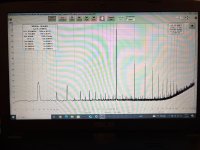
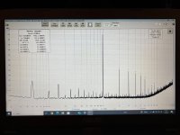
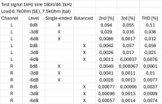
Hi Doede, I did some distortion measurements for my battery powered DDDAC using my laptop PC, REW software, Focusrite Scarlet 2i2 soundcard and a simple attenuator. I think the results are quite expectable for a NOS DAC with passive IV. Please see the attached table and also pictures of the FFT for SE measurement of the left and right channels without upsampling.
The right channel seems to be giving me much lower distortion figures and also the output is half a decibel lower than left channel. Maybe I can adjust these using the current source trimmers on the DAC boards?
The right channel seems to be giving me much lower distortion figures and also the output is half a decibel lower than left channel. Maybe I can adjust these using the current source trimmers on the DAC boards?
Attachments

Hi Doede
I checked resistor on digital input (BCL,DAT,LR) on dddac board V2.0 (without Shunt regul.) all 3 resistor is 100 Ohm and LF on red board is LF33.
Will it work? Or i need change to LF50?
I checked resistor on digital input (BCL,DAT,LR) on dddac board V2.0 (without Shunt regul.) all 3 resistor is 100 Ohm and LF on red board is LF33.
Will it work? Or i need change to LF50?
Nice work Morde, the results are as expected. The small differences are part of two possible variances between left and right. First may be a small difference in the "8-Volt" output of the PCM1794. With 0dB you are very close to the possible internal headroom. And small differences between the bias current (yes, the trimmers) and differences in the value of the load resistors. Those 3 three are all pretty small but might add up in two different directions. Just for fun and curiosity, what are the DC bias voltages against the common pint of the 4 POS/NEG outputs? Also, for fun and science you could repeat the test (forget upsampling) with a -3dB, -6dB and -12 dB signal, which are more representing normal music. you will hardly ever listen to Instruments or voices with exact 0dB level ;-)Hi Doede, I did some distortion measurements for my battery powered DDDAC using my laptop PC, REW software, Focusrite Scarlet 2i2 soundcard and a simple attenuator. I think the results are quite expectable for a NOS DAC with passive IV. Please see the attached table and also pictures of the FFT for SE measurement of the left and right channels without upsampling.
The right channel seems to be giving me much lower distortion figures and also the output is half a decibel lower than left channel. Maybe I can adjust these using the current source trimmers on the DAC boards?
Hi Jeremeysk,
if you have the red board and 3x 100 ohm it might not work as the res board needs a bit of the delay i did in the very early boards with a 1k resistor.
my sugegstion is you take this step by step. Try one board first and if it does not work fine (not or with crackeled kind of distortion, you need to replace the 100 with a 1k.
any ways replace the LF33 with a LF50 for starters
So here’s some more distortion measurements with 0dB, -3dB and -6dB signal levels. Left channel corresponds very well with the earlier measurements but the right channel gives ridiculously low figures. I can’t explain it, I did everything precisely the same as with left channel.
My soundcard is capable of measuring distortion to approx. -110dB level, so with -10dB fundamental the accuracy is about -100dB (0.001%).
The DC offset measurements against the common pin:
L+ 2.83V
L- 2.76V
R+ 2.01V
R- 2.06V
Quite big difference there, maybe I need to adjust?
My soundcard is capable of measuring distortion to approx. -110dB level, so with -10dB fundamental the accuracy is about -100dB (0.001%).
The DC offset measurements against the common pin:
L+ 2.83V
L- 2.76V
R+ 2.01V
R- 2.06V
Quite big difference there, maybe I need to adjust?
Attachments
Last edited:
O wait, there is Something Very wrong. The R channel should also have 2.8 something volt. Is this a 4 deck? That would suggest that one deck R channel is not working correctly, hence the 3/4 value. May be it is the adjustment, but you said they were all at 40mV ? Check if 8 volt is present at all decks and 40mV is real there… 100% sure the Rload are the right value? Any possibility of poor solderjoints so a part is not working correctly ?
Ha, that’s it. Something funny with the R channel bias circuit when I measured it with a DMM. At first the reading was 31mV but after I poked it a little the value jumped up to 41.4mV, while the left is 41.6mV. Now the DC offsets are for the R channel
R+ 2.77V
R- 2.77V
So, a bad connection somewhere or the trimmer is bad. Thanks for pointing this out for me!
R+ 2.77V
R- 2.77V
So, a bad connection somewhere or the trimmer is bad. Thanks for pointing this out for me!
Hi Doede,
I'm looking to repurpose my 5V DDPSU to a 24V output. It looks like the Talema PCB mount ones max out at 22V parallel, so do I need one that is 30V parallel? I'm a bit confused because it looks like the existing Talema transformer is wired in series, which should put out 18V but in the description of the PSU you mention it should be 6 volts higher input than output. I'm sure I'm missing something here 🙂 Any guidance you can provide would be helpful. For context, this is for a low draw phono pre, so low amperage is no problem.
Thanks for the years of enjoyment I've gotten from this DAC!
Per
Hi Per,
A few thoughts to this:
Look at the circuit please, you will see that it is a half bridge setup. Not "real" series. 24 DC Output needs minimum 30VDC input, so you could use a 24Vac transformer with two windings sec. make sure to have Capacitors capable of 40V DC
A few thoughts to this:
Look at the circuit please, you will see that it is a half bridge setup. Not "real" series. 24 DC Output needs minimum 30VDC input, so you could use a 24Vac transformer with two windings sec. make sure to have Capacitors capable of 40V DC
Just finished another DDDAC build (number 4 for me). A little late given the new boards, but still excellent!
IanCanada stuff: Q3 Fifo, sinePi, reclockPi,
Neutrino2 clocks
Salas L-adapter for 5.1V (Raspbery Pi, Pi Pico for volume control)
Salas L-adapter for 10.5V (DDDAC without 7810s fitted - jumpers installed instead)
DieNoizer (Thanks tombo56 for the Gerbers!) at 12V for the clocks that also feeds a Sparkos 3V3 for the FifoPi
AMB volume control board arranged for constant output resistance (1K). The Sowters see between 1K and 2K ohms and I cannot measure any frequency response anomalies.
Elna Silmic for all electrolytics on the analog sides of the DDDAC.
The only source for this system is this DDDAC streamer - so no preamp. With the Sowters set for 1:2, drives my amps just fine.
And no power switch - my DACs stay on 24/7.
Thanks to Doede! Absolutely amazing DAC.
And to the folks at AudioCreative! I used much of their blog info.
I am using 45.158400 and 49.152000 MHz clocks. I have a few files at 352K and 384k. (The 2L stuff is quite nice.)
I have Neoprene foam tape under the clocks on top of nylon standoffs.
Links for gerbers:
AND
I have Neoprene foam tape under the clocks on top of nylon standoffs.
Links for gerbers:
PCB V2
Here is revision of the single rail dienoiser pcb.
It now accommodates 18 mm diameter input caps. There is led indicator on the output with capacitor bypass, so it is assured that no noise will be introduced (overkill, I know). R5 resistor is moved close to output pin of LM317. Pitch for BC transistors is changed to 2,5 mm. Wonder why? I was lazy to exchange soldering tip for fine one and all pins were soldered together. That made me to replenish my curse words repertoire.
Output capacitor can be with 5 mm or 7,5 mm pitch and up to 16 mm diameter. There is position for a ESR...
Reversed LED polarity error
While adding LED pilot indicator my brain decided, without notifying me, that LED diode should be reversed polarity like Zenner diode. Today, some leftover brain cell kicked in and I spotted mistake.
If anyone ordered the pcbs it’s no big deal. Just mount LED in reverse to markings on the silkscreen. Corrected gerbers in attachment. Sorry for any inconvenience.
- Home
- Source & Line
- Digital Line Level
- A NOS 192/24 DAC with the PCM1794 (and WaveIO USB input)