I was also confused about this with DDDAC for a long time, and I tried different grounding schemes. Here's a document that Doede made a while ago.
I've studied that and as I see it this is what I have and need to do:
RPI > DAC > RCA's > Amp
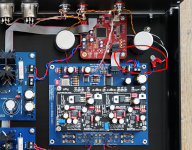
From the diagram and from looking at the images on the Creative Shop I see that the Mainboard has it's -Ve connected to chassis ground.
Since the rest of the system is connected by common ground via the -ve lines then I assume that a single connection from the IEC socket Earth to chassis should be sufficient for safety, and presumably for best audio?
Attachments
Say I don't have the safety ground in place (think dac on a board), will this affect sound quality, or is it first and foremost safety?
tricky and hard to say. I have found out, that when the safety earth is consequently implemented in the right way - no signal going through it and no loops - it helps to keep the background in the music more quiet. this for the whole chain.
tricky and hard to say. I have found out, that when the safety earth is consequently implemented in the right way - no signal going through it and no loops - it helps to keep the background in the music more quiet. this for the whole chain.
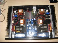
I have found the same result. I use the safety earth as intended i.e. the safety earth is only connected to the metal case or enclosure in one place.
There is no reason for the safety earth to be connected to any part other than the case.
See where I have connected the safety earth. I get no hum or any problem at all.
Attachments
I'm still trying to find out if most people connect the -Ve of the Mainboard to the Chassis? It is clearly shown in the Creative Shop built DAC's but perhaps Doede can confirm this is the recommended way to do it?
I'm at the stage where the DAC is working but I am afraid to ground any boards without double checking it's OK to do so.
I hate the magic smoke 😉
I'm at the stage where the DAC is working but I am afraid to ground any boards without double checking it's OK to do so.
I hate the magic smoke 😉
Grounding is a confusing issue. Here is a link to a technical note from Rane corporation on grounding.Grounding and Shielding Audio Devices
There is a lot of helpful info on the Rane site IME.
There is a lot of helpful info on the Rane site IME.
Last edited:
I have a single board kit here and am getting together chassis and power supplies etc. I have a question. What are the solder pins for in the main board parts package used for?
Is there any point of upgrading the electrolytic caps on the main and dac boards during the initial construction? I've tried to read through the history on this but it got confusing. At this point, with the new version in production for a year or so, is there any consensus on this?
Is there any point of upgrading the electrolytic caps on the main and dac boards during the initial construction? I've tried to read through the history on this but it got confusing. At this point, with the new version in production for a year or so, is there any consensus on this?
I get Cinemag CMLI-600/600C today.
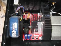
I'm 2 deck DDDAC now. I bulding Cinemag CMLI-600/600C in my dddac .
It have big noise on sound ,what happen?
I'm 2 deck DDDAC now. I bulding Cinemag CMLI-600/600C in my dddac .
It have big noise on sound ,what happen?
Can you show us by diagram or perhaps explain how you connected the transformers? It sounds like you may have a wiring error.
First of all I would try to keep things simple. That means taking out volume control out of your circuit.
Secondly it looks like you've only loaded on side of the dac's outputs. Or are you going to use it SE?
Secondly it looks like you've only loaded on side of the dac's outputs. Or are you going to use it SE?
Last edited:
First of all I would try to keep things simple. That means taking out volume control out of your circuit.
Secondly it looks like you've only loaded on side of the dac's outputs. Or are you going to use it SE?
its DAC->Cinemag CMLI-600/600C->volume control->RCA
I use cap before, its ok.
what is SE?
SE is abbreviation for Single Ended.
To get the most out of the transformer you should consider using it in balanced mode. That way you get twice the output. You would connect the primary side across the + and - outputs of the DAC, no cap required, and the secondary can then be connected to either a single ended or balanced circuit. Most of these transformers have shields and case grounds that need to be terminated as well as the signal connections. Review the transformer diagram to make sure you have the windings properly connected. You should be able to measure the dc resistance of the windings with an ohm meter.
P.S. I just had a look at the datasheet for the transformer. I would connect it like the Test Circuit 1 diagram at the bottom of the page using the 2 balanced DAC outputs from the tops of the 133 ohm resistors as the input to the transformer and then connecting your 10k output pot to the output side of the transformer. The shield and case connect as in the diagram. Case to chassis ground and shield to audio common.
If you still can't get any sound, disconnect the transformer completely and make sure the DAC is working in stock form. Perhaps there is another problem.
Can anyone here tell me what those solder pins are for in the main board parts kit? There is an assembly manual for the DAC board but nothing for the main board.
help !
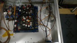
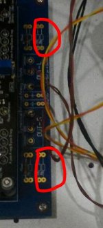
you need to put resistors here to make it work properly. With the transformer output you use both dacs (pos and neg) and one is not biased as you see.
with capacitor (SE) you have no problem as you only use one dac
also, volume pot should always be at the receiving side of things. the low output impedance (good for driving the interlink) is now thrown away.
the last point is audio tip, has nothing to with the noise. that is just adding the two Rload resistors
good luck !
doede
Attachments
Can anyone here tell me what those solder pins are for in the main board parts kit? There is an assembly manual for the DAC board but nothing for the main board.
They are used for the outputs like POS, NEG and COMMON...
From that (terrible) photo he posted, I'm pretty sure he magnetised those transformers quite nicely...
From that (terrible) photo he posted, I'm pretty sure he magnetised those transformers quite nicely...
Good point ! There must have been quote some DC at the primary....
Beter Google how to de-magnetisme them behoren further usage
Hi there, I have a DDDAC kit on order which will use 3 x DAC's.
Wondering about the load resistors using capacitor coupling.
So RL=134/3=44.66 ohm
So using E24 range 47//920=44.69 ohm a +0.2% variation
Does this look correct, cheers Johno
Wondering about the load resistors using capacitor coupling.
So RL=134/3=44.66 ohm
So using E24 range 47//920=44.69 ohm a +0.2% variation
Does this look correct, cheers Johno
Hi there, I have a DDDAC kit on order which will use 3 x DAC's.
Wondering about the load resistors using capacitor coupling.
So RL=134/3=44.66 ohm
So using E24 range 47//920=44.69 ohm a +0.2% variation
Does this look correct, cheers Johno
yes it does. Not sure what will be shipped. I assume 134 +68 Ohm which gives 45,1 which is also perfectly fine. Plus/minus a few ohms does not hurt at all
- Home
- Source & Line
- Digital Line Level
- A NOS 192/24 DAC with the PCM1794 (and WaveIO USB input)