Hey super Enrico!
Doing good thanks ��������, thanks for your advice.
I have been looking on Farnel for the SAMTEC pins but can't seem to quite find the right male/female ones, do you have a link or a product number?
I completed the 1/2 clock upgrade yesterday but not tested it yet, really looking forward to putting this dddac back together.
Ciao James 🙂
I order the SAMTEC connectors directly to the SAMTEC website. You can register and order how many parts you want. They have a very nice service and the shipment is really cheap. This the part number of the connectors that you need SSQ-101-04-F-S and this is the link to the website https://wwws.samtec.com/
Cheers,
Enrico
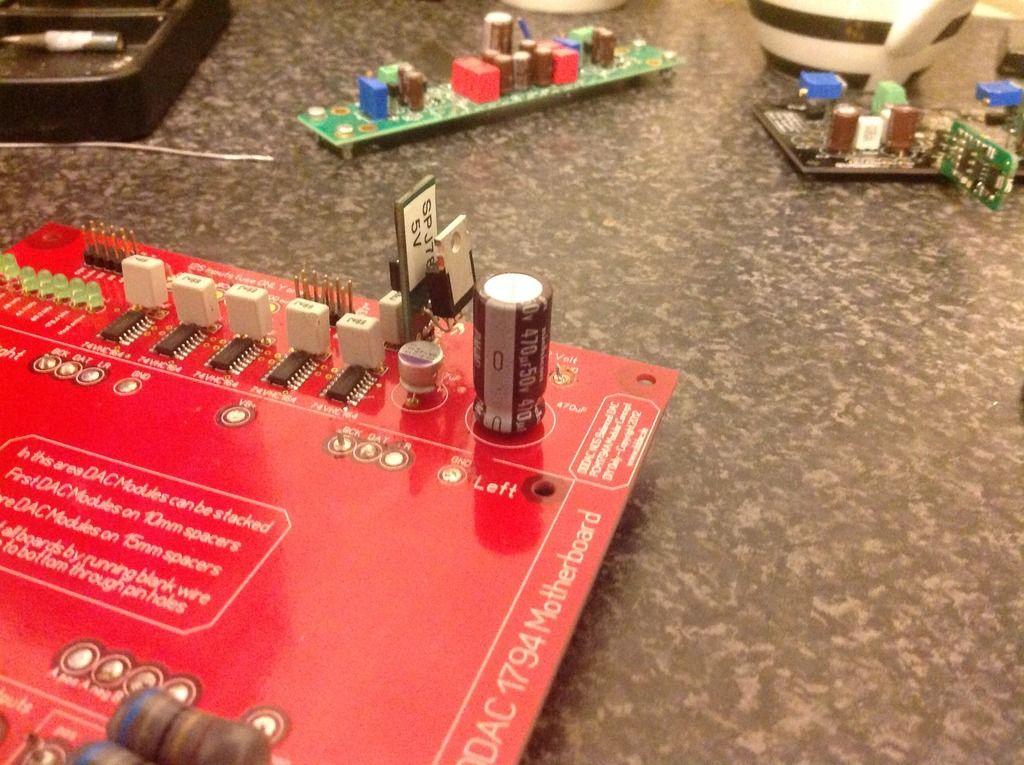
I have fitted a Belleson SPJ78 5V on the red board along with the 1/2 clock on the underside of the board. I think the SPM was all I needed, but is it ok to use the SPJ?

My DDDAC started making some nasty crackling noises, and I am wondering where to look. From the sound of it, I'd guess it's somewhere in the digital world. The crackle only appears when music is playing.
I've worked quite a bit on my DDDAC during the past few weeks to get my TVC working well with my active xover (see here). Once I got this working nicely, I put the DDDAC back into the audio system, and there was the crackle... As far as I can tell, I have not touched the DDDAC or the DAC boards themselves, so I guess I may have screwed up something attached to it. GND connections maybe? Should I connect the analog GND or the digital GND? Where?
I'd be glad to get some debugging ideas...
Red Board Belleson 5V
I use the Belleson SPM on my red boards with half-clock and it doesn't even get warm. I use the SPJ78 with a heat sink on my WaveIO to provide 400ma. Using the SPJ78 on the red board is like shooting squirrels with a Howitzer - it works, but.....
Your red board has all the upgrades I use, however, I don't see an extra 330-470 ohm load resistor across the 5V to force the Belleson to operate at least 15ma to regulate better.
I have fitted a Belleson SPJ78 5V on the red board along with the 1/2 clock on the underside of the board. I think the SPM was all I needed, but is it ok to use the SPJ?
I use the Belleson SPM on my red boards with half-clock and it doesn't even get warm. I use the SPJ78 with a heat sink on my WaveIO to provide 400ma. Using the SPJ78 on the red board is like shooting squirrels with a Howitzer - it works, but.....
Your red board has all the upgrades I use, however, I don't see an extra 330-470 ohm load resistor across the 5V to force the Belleson to operate at least 15ma to regulate better.
Thanks for your help Carlsor
Yes I ordered the wrong Belleson product, but if it works then great.
Regarding the load resistor, would this one be suitable ?
RS02B400R0FE12 | Vishay RS Series Axial Wirewound Resistor 400Ω 1% 3W 20ppm/C | Vishay
Yes I ordered the wrong Belleson product, but if it works then great.
Regarding the load resistor, would this one be suitable ?
RS02B400R0FE12 | Vishay RS Series Axial Wirewound Resistor 400Ω 1% 3W 20ppm/C | Vishay
Yes - 3W is overkill but no problem. This resistor should work fine and give 12.5ma of additional load and generate .0625 watts heat. A 1/4watt resistor would be sufficient, but I find that parts already on hand are the cheapest. A 1 watt wire wound is more than enough if you are buying one.
Last edited:
Hi everybody ! 😛
it's been a long time that I listen to music with my lovely DDDAC and now it's time to finish it... The WAF need to be increased, one year and a half with chokes and others transformers on the floor, Dac taking dust...
I would like to put everything in a nice case but... I still have the issue with a kind of distortion on the left channel, especially when I listen to music quietly.
The problem appears more and more oftently.
I suspected a bad solder so I have checked them but nothing found.
I realized last week that if I touch the caps on the dac during the problem appears, or the neg part of cinch, the distortion changes a little but remains.
If I connect the ground of the mainboard close to the PS's plug with the NEG of the right channel, the distortion on the left channel stops (volume of the right channel decrease but I think that this is normal).
I would like to avoid to disassemble the fourth board so I ask you before doing it if you had any idea ?
Reminder, I have a four boards dddac, with separate LCLC PS for analog. The issue occured last year when I have separated the analogue PS from the digital PS
Probably bad solder but do you think that it is on digital side or analgue side ? No crackle, no cut, it really a kind of distortion.
Many thanks for your help !
Julien
The issue occured last year when I have separated the analogue PS from the digital PS
I have separate PS for the analog and digital on my DDDAC. Do you have a wire connecting the grounds of the two power supplies to each other? I have done this with all my DDDAC builds and have never had the problem you report. The combined ground is connected to chassis ground and which is connected to the AC neutral.
Last edited:
No, I didn't had cutted any path on the PCB so I thought that grounds were connected.
The Strange thing is the fact that it works perfectly most of the time.
The Strange thing is the fact that it works perfectly most of the time.
I have separate PS for the analog and digital on my DDDAC. Do you have a wire connecting the grounds of the two power supplies to each other? I have done this with all my DDDAC builds and have never had the problem you report. The combined ground is connected to chassis ground and which is connected to the AC neutral.
I use exactly the same arrangement with no issues-just great sound! Are you using a buffer board output stage? If so, ground of that psu also needs to go to your star earth point
Thanks for your replies !
No buffer board...
Yesterday, I reinstalled everything on a final wood board, with new PS for digital side and BBB + Wave IO (2 differents PS).
Then, I tried today and the result was worst than before, I had distortion on both channels.
So I decided to remove the top DAC board, and did an essai with the tree others. Without changing the résistors, it sounds great ! 😱 No more issue so I will try to reinstall the fourth dac board.
I noticed that the analog voltage grown to 10.5V, instead of 9.8V when the four boards are in place. The problem could not came from here ?
I think it could. 1.8v may not be enough headroom for the regs
Just to make sure
The absolute minimum power supply voltage ( the "12 Volt" one) is 11.5 Volt as there is a 10 Volt pre-regulation.
Ok, many thanks, I will try to increase the PS voltage by adding a cap between the transformer and the first choke. Now I have this:
It feeds the LF80's circuits, I don't understand what do you mean by "there is a 10 Volt pre-regulation" ?
An externally hosted image should be here but it was not working when we last tested it.
It feeds the LF80's circuits, I don't understand what do you mean by "there is a 10 Volt pre-regulation" ?
billyboik @
Instead of putting a cap between trafo and first choke, you can try to change from serial common mode on your last choke to parallel connection. Then you will have more volt and still have a true choke input psu. Try to avoid a cap before the first choke, it sounds better without.
Instead of putting a cap between trafo and first choke, you can try to change from serial common mode on your last choke to parallel connection. Then you will have more volt and still have a true choke input psu. Try to avoid a cap before the first choke, it sounds better without.
Good idea ! I was not very satisfied to quit choke input mode. I could also change my transformer but I bought it some weeks ago...
Hello Billy,
Using the ll1638 which has a current rating of 200mA will not work if you are using 4 new day boards.
Dcr of each coil is 18 ohm so that will give a BIG voltage drop. You could use the ll1694 as the input choke. You can read my posts in this thread somewhere I did write what transformer I am using.
I see you split left and right so it could be OK with 200ma choke but istill would trytoswitch the lundahls.
Greetings, eduard
- Home
- Source & Line
- Digital Line Level
- A NOS 192/24 DAC with the PCM1794 (and WaveIO USB input)