Thanks !
Hello !
Good news, adding a 1.8uf and 68k resitor between dac's output and AVC have dramatically improved the things.
No more "ploc" on the rotary switch and I would like to say no more distortion... but I'm not sure. Maybe now I am too focused on it and I hear Something that is not a problem.
I will try to replace the RC by the cinemags but for the moment I don't remember how to connect it.
Still unexplained mysteries:
why the issue appeared and disappeared itself ?
why it was ok with only three dac modules ?
why now I have so much DC offset ?
I don't know, but I would to understand.
Thanks very very much everyone !
To be continued...
Julien
EDIT: Unfortunalety I tried to listen to music quietly and the problem is still there 🙁
You have quite some DC across the input of the autoformer. This may saturate the core, and cause distortion. Could this be your problem?
Hello !
Good news, adding a 1.8uf and 68k resitor between dac's output and AVC have dramatically improved the things.
No more "ploc" on the rotary switch and I would like to say no more distortion... but I'm not sure. Maybe now I am too focused on it and I hear Something that is not a problem.
I will try to replace the RC by the cinemags but for the moment I don't remember how to connect it.
Still unexplained mysteries:
why the issue appeared and disappeared itself ?
why it was ok with only three dac modules ?
why now I have so much DC offset ?
I don't know, but I would to understand.
Thanks very very much everyone !
To be continued...
Julien
EDIT: Unfortunalety I tried to listen to music quietly and the problem is still there 🙁
Last edited:
Some tests...
Removing of the fourth dac module and changing R load to 47R -> same issue
Removing the choke's PS and replaced it with simple regulated 12V PS -> same issue
Next step ? I will remove all the dac modules and go back to standard configuration, one by one.
I noticed something, by cutting the pcb path after R1, the LF33 is directly connected to PS, the origin could'nt been generate from this ?
Others...
Trying to feed the mainboard with SPDIF instead of BBB+WaveIO -> same issue
Replacing the AVC with ALPS pot -> same issue
Now I'm crazy
Trying to feed the mainboard with SPDIF instead of BBB+WaveIO -> same issue
Replacing the AVC with ALPS pot -> same issue
Now I'm crazy
Remove one dac board at a time.and test, you may have damaged a/all dac chips in the stack.
Sad but possible.
Sad but possible.
Hello !
Good news, adding a 1.8uf and 68k resitor between dac's output and AVC have dramatically improved the things.
No more "ploc" on the rotary switch and I would like to say no more distortion... but I'm not sure. Maybe now I am too focused on it and I hear Something that is not a problem.
Ok, so blocking the DC from the autoformer seems to help. I wouldn't be surprised if you'd get a resonance from the capacitor/autoformer though (that may be the "I'm not sure" part).
I see two reasons why blocking DC could help:
1. Avoiding magnetic saturation of the autoformer.
2. Avoiding too much load on the outputs of the DAC chips. What is the DC resistance of the autoformer? If it's too low, it might just sink too much current from the DAC chips, resulting in distorted output from the chips.
I'd guess reason (1) is more likely, but I really don't know.
I will try to replace the RC by the cinemags but for the moment I don't remember how to connect it.
Just remove the R, C, and autoformer. Attach the primaries of the Cinemags to the 'POS' and 'NEG' outputs on the DDDAC mainboard. For volume control, you can use a potentiometer at the secondaries of the Cinemags. Or just use software volume control for the time being (for debugging purposes).
Still unexplained mysteries:
why the issue appeared and disappeared itself ?
why it was ok with only three dac modules ?
why now I have so much DC offset ?
The DC offset is normal, that's part of the DDDAC design. The DC voltage is the result of the output bias current(s) of the DAC chip(s) flowing through the I/V resistors to GND. The "I/V resistors" convert the output current to the signal voltage at the output of the DDDAC board. Did you adapt the "I/V resistor" values to the number of DAC decks (see DDDAC instructions)?
The DAC chips have a balanced output (positive and negative current). The POS and NEG bias currents result in POS and NEG bias voltages that are (almost) identical, so the DC voltage difference from POS to NEG is (almost) zero. That's why you can use the Cinemags (or similar output transformers) without saturating the core. I believe this won't work with your autoformer, because the autformer needs to be connected to the COMMON ouput.
Overall, I'd suggest to make your DDDAC work without the autoformer first. This will make it much easier to isolate your problem(s). Just use the standard configuration with a film capacitor from the POS output to the RCA out, and COMMON to the RCA GND (see DDDAC instructions). Once this works, you know the DDDAC is ok.
Then you can try to add the autoformer. However, I think a "full" TVC instead of the autoformer may be better, because this allows you to use the balanced POS/NEG outputs, which are (almost) free of DC (instead of POS/GND with the full DC bias). I use the Sowter 9335 TVCs in my DDDAC, and they work very well.
I can think of no reason the autoformer could not go across the pos and neg outputs to gain the lack of dc, it will sum the output swing from them both and give a higher output level, the current common could be just connected to the neg. Unless the sowters have a centre tap to common.
Hello Billy,
FIRST try to get it working the way it is described in the Manual!
It appears you probably did invent something that in the end is not working or even did destroy something while doing this.
A cold solder joint is hard to find and easily made if you are doing to many things at the same time.
Try to get it working with just one dac board at the time. If you will get 4 times the same results it might be that the problem is on the main board or something is wrong with all of the 4 boards.
Or wait for Doede to suggest something. The solution could be easy but I think you did start to soon to do things differently than the way mentioned in the manual and now you are facing a problem which appears to have nosolution.
Again I would wait for Doede maybe he can suggest an easy way to solve your probl r my.
Greetings, Eduard
I can think of no reason the autoformer could not go across the pos and neg outputs to gain the lack of dc, it will sum the output swing from them both and give a higher output level, the current common could be just connected to the neg.
The GND connection of the RCA out would then be connected to NEG on the DDDAC board. That sounds like asking for trouble with signal GND to me.
Unless the sowters have a centre tap to common.
The transformers don't have or use a centre tap on their primaries (not the special DDDAC Sowter, nor my TVCs, nor the Cinemags commonly used with the DDDAC). What would be the purpose for that?
The difference between these transformers and an autoformer is that they have separate primary and secondary windings. One end of their secondary winding can therefore go to signal GND, independently of where the primaries are. This is not possible with an autoformer.
Apologies, just went back and looked at the pic again, you are quite correct!
Took the numbers as the secondary, not awake enough and using the phone doesn't help!
Took the numbers as the secondary, not awake enough and using the phone doesn't help!
wow, this is a complicated thing. Hard to get a clear picture what is being done with this.... But one thing is clear, by using av transformer, you MUST connect between POS and NEG. The common must not be used. The only way to it it right is with a secondary winding which will deliver a new "GND" (pick one of the poles) and this might be connected to GND of the dac, but must not. I do not do it, and I avoid any ground loop back to the amplifiers with that.
Not sure if the TVC is really a autotransformer? Because that will cause serious trouble as you connect the POS or NEG to the ground system. Also a DC path through the transformer.
I agree with Ed, pls build a working DAC first, than start adding one by one other things. It will make clear when stuff goes "wrong" now it is a cluster F...k
Hello Billy, Doede and the rest,
The problem isn't in the power supply probably unless you did connect the circuit to a voltage that is way to much so that the voltage regulator transistor did get to hot. ( in the beginning I was thinking you did use the boards with the Tent shunts )
FIRST I would make it with an output capacitor. Use one dac board change the load resistor to the correct value. Add the second board change resistor, add third board change resistor and finally fourth board and change resistor one more time.
THEN if it is still working, no strange distortion you could replace the cap and connect the autotransformer the way Doede did tell us how to Do!
THEN it should work.
If not we will all get crazy.
First make it work like it should work and then start modifications. But be carefully if you are not sure it will work better ask first. Changing a choke , a capacitor or resistor in the power supply is easy and once you know how to do it will work. But the circuit itself be carefully before destroying anything.
Good luck!
Greetings, eduard
Hello everybody 🙂
First, I would like again to thank all of you for your precious help 😉
Second, I have a DDDAC which works! After removing 3 dac's module, without forgetting to try each time, with correct R load, the last one plays without any distortion 😀
I have seen "soudure creuse" (I don't know the name in English, maybe "cold joint") on the second module. So know, I'm going to re-build the tower, and re-haeting all the joints 😉
Hello everybody 🙂
First, I would like again to thank all of you for your precious help 😉
Second, I have a DDDAC which works! After removing 3 dac's module, without forgetting to try each time, with correct R load, the last one plays without any distortion 😀
I have seen "soudure creuse" (I don't know the name in English, maybe "cold joint") on the second module. So know, I'm going to re-build the tower, and re-haeting all the joints 😉
Is this with the autoformer? If so, let's hope it really was a problem with the cold solder joint. But there's still a possibility that the problem is related to the autoformer. Less DAC chips means lower total DC bias current, and therefore less saturation in the autoformer. Keeping fingers crossed!
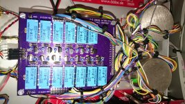
FIY I attached a photo of my TVCs in the DDDAC (yes, the cables are a mess). The relays are used to select the different taps on the TVC secondaries. There is another relay board underneath the one on the photo, and the whole thing is controlled by an Arduino microcontroller. Works well so far...
Attachments
Hello Billy,
Google for how to deal with cold solder joints., it requires more than heating it up a second time.
After having a 4 board dac working you could take alook at the value of the 100 ohm resistor.
The input choke is seen as a 0,16 H . Because you have serious voltage drop across the second choke I guess the dc voltage at the first cap will be around 20 volts. So to make it work as a true choke input you need a minimum current of 20/0,16 is 125 ma. Better be safe than sorry and don't use the load fromthe dac too. Resistors always work but your dac did not. Right nowyour100 ohm will give 200 mA with 20 volts so that could be lower. No need to make that current bigger than it should be. A little higher OK.
You willget less rippleifyou reducethe bleeder current closer to the optimumvalue
Greetings, eduard
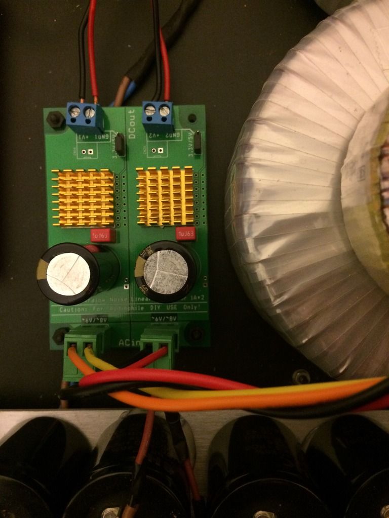
hi guys, after a bit of help if that is ok. I am wanting to power the digital side of the DAC, I believe I need about 6V, each side of this PSU puts out 3.3V. In my naivety I thought I could link the positive of both sides of the PSU together to give me 6.6V but that isn't the case it still puts out 3.3V with both sides combined. Where am I going wrong?
Thanks
Thanks

hi guys, after a bit of help if that is ok. I am wanting to power the digital side of the DAC, I believe I need about 6V, each side of this PSU puts out 3.3V. In my naivety I thought I could link the positive of both sides of the PSU together to give me 6.6V but that isn't the case it still puts out 3.3V with both sides combined. Where am I going wrong?
Thanks
It seems that you plugged it in parallel, if you want to add the voltage, you must plug it in serial 😉
Hello Billy,
Google for how to deal with cold solder joints., it requires more than heating it up a second time.
After having a 4 board dac working you could take alook at the value of the 100 ohm resistor.
The input choke is seen as a 0,16 H . Because you have serious voltage drop across the second choke I guess the dc voltage at the first cap will be around 20 volts. So to make it work as a true choke input you need a minimum current of 20/0,16 is 125 ma. Better be safe than sorry and don't use the load fromthe dac too. Resistors always work but your dac did not. Right nowyour100 ohm will give 200 mA with 20 volts so that could be lower. No need to make that current bigger than it should be. A little higher OK.
You willget less rippleifyou reducethe bleeder current closer to the optimumvalue
Greetings, eduard
After installing the second board, the distortion is back 😡
I have forgot the de-solder station at work, I will bring it tomorrow, I stop now, I'm tired and fed up with this distortion.
Have a good night/morning 😉
After installing the second board, the distortion is back 😡
I have forgot the de-solder station at work, I will bring it tomorrow, I stop now, I'm tired and fed up with this distortion.
Have a good night/morning 😉
Is this with the autoformer in place? Make sure you remove the autoformer and just use the standard DDDAC capacitor output.
Is this with the autoformer in place? Make sure you remove the autoformer and just use the standard DDDAC capacitor output.
Both, one channel with cap + alps pot, other channel with cap + autotransformer, same result 🙁
It seems that you plugged it in parallel, if you want to add the voltage, you must plug it in serial 😉
Brilliant, thanks for your help!
- Home
- Source & Line
- Digital Line Level
- A NOS 192/24 DAC with the PCM1794 (and WaveIO USB input)