Quick reaction just to make sure there is no misunderstanding:
....Seems Doede wasn't too impressed with the 338 vs 318......
This was in the light of the significant higher cost and "how much" they were better" I actually kept (now I actually have them) the 338 in my other DAC (with FiFoPi Q2) as they show some improvement, but as said, the 318 give almost same good performance at clearly lower price
Yes, the difference is small, if any at all between 318-338. I think a ReclockPi will give a bigger improvement than going from Accu 318 to 338.
hi! i am using 2 decks and capacitor output. should i buy the cinemags? i have read that bass is weaker with cinemags. could someone describe the difference?
Thanks DD. I think around 480mA is close to half of the mA drawn by 4 of the new boards (200mA*4). I played a 24/192 file and observed the current draw rise to 554mA. This is roughly half of the consumption of the new boards.
Hey there, yes I do have a spare pair of the 15/15B trafos. You could PM me and we can explore if it can work out.
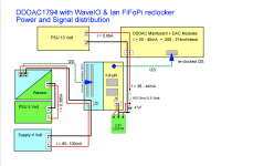
Had a question for all fifopi users here. As per the attached diagram, DD recommended a 163ohms resistor at the J5 position along with a 47uf cap. Could any of you clarify the following:
1. Is this 163ohm value sacred or could I use a nearby value such as 160 or 180 ohms?
2. Will using good quality parts - this resistor and the 47uf cap make improvements to the sound or another way to put it is that is this path critical enough to be putting say something like an AudioNote Niobium resistor or an Allen Bradley for that matter?
Attachments
Hi Kartick,
1. NOT at all. it even depends on the clocks used (How much mA they draw) and that is actually the R*I voltage drop I am sparing the Regulator to dissipate as heat.
2. I would use regular components....
1. NOT at all. it even depends on the clocks used (How much mA they draw) and that is actually the R*I voltage drop I am sparing the Regulator to dissipate as heat.
2. I would use regular components....
Thanks DD for a quick response. I am currently using the fifopi with the ACCUSILICON AS318-B-451584 & ACCUSILICON AS318-B-491520 clocks. Will the following R & C combinations work out fine in place of 47uf & 163ohms?
- 160ohms & 220uf
or
- 100ohms & 470uf
Planning to put in Nichicon KZ/FG/FW.
- 160ohms & 220uf
or
- 100ohms & 470uf
Planning to put in Nichicon KZ/FG/FW.
Just start with 160 - ish. Ohm and measure the voltage behind the R, at the input of the Regulator. If you see like 4-6 volts it is ok. Otherwise change the value
The capacitor is not critical, I used 47uf as I have them Lying around in quantity (part of the dddac kit)
The capacitor is not critical, I used 47uf as I have them Lying around in quantity (part of the dddac kit)
With my 160ohms/47uf cap, I measured as you said and was getting around 4.7V; which translated to around 29-30mA of current draw from J5 of fifopi. I guess this is ok. I will try a 100ohm/220uf combo for slightly more aggressive filtering.
hi kartick! i sent you pm for spare cinemags
Apologies, have now responded to you.
Hello Kartick,
Just some random advice.
Because of the low current there wont be much or no benefit at all from using a bigger cap.
Probably a better cap positioned close to the regulator circuit could give some improvement.
Recently Doede made a special edition of his regulator board which will also allow me to change the RC network for the error amplifier into an LC network with similar serie resistance ( 330 ohm).
He could indeed measure an improvement.
If you have some space available you could do the same by using a Hammond choke with 100 to 160 ohm serie resistance and 50 to 100 mA current rating. The 153-159 series are easy to install.
If you take the 156L it is 5 Henry, 75 mA and 135 ohm and it is small and around 20$.
There are more '' luxury '' chokes available but this one should be see as an alternative to a .50$ resistor. The LC is a 12 db filter and the RC is just 6.
Greetings, eduard
Hello Kartick,
Just some random advice.
Because of the low current there wont be much or no benefit at all from using a bigger cap.
Probably a better cap positioned close to the regulator circuit could give some improvement.
Recently Doede made a special edition of his regulator board which will also allow me to change the RC network for the error amplifier into an LC network with similar serie resistance ( 330 ohm).
He could indeed measure an improvement.
If you have some space available you could do the same by using a Hammond choke with 100 to 160 ohm serie resistance and 50 to 100 mA current rating. The 153-159 series are easy to install.
If you take the 156L it is 5 Henry, 75 mA and 135 ohm and it is small and around 20$.
There are more '' luxury '' chokes available but this one should be see as an alternative to a .50$ resistor. The LC is a 12 db filter and the RC is just 6.
Greetings, eduard
Thanks Ed. Let me explore this option as well. I am just trying to understand that on one hand, there is a school of thought that even the quality of RC doesn't matter on this path and then on the other hand we are trying to explore that we want to go the LC route to gain benefits. Anyway, I will replace the RC with better parts and see if there is any detectable improvements. Also, will arrange a choke and try it too.
Hello.
The quality of the parts of the RC will VERY probably not make a huge difference. I am no technician but i can imagine that you can make the cap to big.
First thing to take care of is getting the right voltage so the the regulator will work properly.
In the attachment you can read about the benefits of a choke when used in in a choke input power supply. LC is 12 DB so it will do a better filtering than a 6 DB RC
In your situation the input voltage going to your regulator is already pretty clean because it comes from Doede's regulator. But by adding a LC network and not a RC one you will get better isolation between the circuit being fed by Doede's regulator and the clock circuit with its own regulator.
It is not a big investment so that is one more good reason to give it a try.
Greetings, eduard
Attachments
Hello.
The quality of the parts of the RC will VERY probably not make a huge difference. I am no technician but i can imagine that you can make the cap to big.
First thing to take care of is getting the right voltage so the the regulator will work properly.
In the attachment you can read about the benefits of a choke when used in in a choke input power supply. LC is 12 DB so it will do a better filtering than a 6 DB RC
In your situation the input voltage going to your regulator is already pretty clean because it comes from Doede's regulator. But by adding a LC network and not a RC one you will get better isolation between the circuit being fed by Doede's regulator and the clock circuit with its own regulator.
It is not a big investment so that is one more good reason to give it a try.
Greetings, eduard
Oh okay, sure, I will check with my friends if they have a spare choke with the specs you mentioned, lying around with them. If yes, I will quickly put it to test.
Hello,
If you have a 2 Henry 50 ohm 100mA you can just add a resistor in series a get the right DC voltage on your regulator.
My regulator had a 330 ohm plus 47 cap and Hammond has a 7 Henry 40 mA 340 ohm choke. Of course you can choose one that will allow you to make a clock change in the future. Probably wont make sense to use a 1 Henry 500 mA . It will work but i guess more Henry and current rating a bit closer to the actual situation will work better.
Like you can read in the article a choke works both ways.
Right now i cannot find the simulation Doede made for adding the 7 Henry choke to his regulator circuit.
Greetings, eduard
@Doede
Hi. I somehow have messed up my standard DDDac 12V psu and could need a little help.
It started when I tried to implement the Choke tweak using a 15mH/0.36Ohm Mundorf Choke and a 1.3Ohm ceramic resistor in serial. The resistor value was from mbrennwa's advise some time ago.
I removed R2 and inserted the Choke/Resistor in its place, but I left the fuse in the circuit because I'm a chicken ;-) I also changed the C3 from 4700uF to 22000uF... or so I thought. It was the C1 I changed by accident.
I now measured approx. 19.4V DC and that value couldn't be adjusted at all.
After consulting with bubu200 I was informed of my mistake and I put C1 back to 4700uF and changed C3 to 22000uf.... but that changed nothing. Still 19.4V DC (which btw makes sense!).
I now removed the Choke/Resistor and put back the org. R2. That gave a strange DC reading and a moment later the fuse blew. A new fuse didn't blew right away but I still had 0V DC output. I couldn't read any voltage on the MBR20200CT Schottky Rectifier so I assumed that this one also blew.
Now I have changed the Rectifier and the fuse (which now also was dead???) and I now measure approx. 11V DC with a 9V Transformer but it still cannot be adjusted at all. Also the LED2 (I think) isn't lighting up.
Could the T1, T2 or T3 transistors be blown? A dead T3 could explain the LED2 problem...I think.
I didn't change the fuse to 2A which I believe you recommended, but that couldn't cause the components failing in the first place? Could it?
A little more info.
- I did the same tweak on my secondary DDDac using 10mH/1.0Ohm and a 10000uF cap in C3. That worked right away without any problems and with a 1A fuse.
Greetings and thank you 🙂
Reading all the symptoms, it is clear you had a chain of events and something else went wrong, which you did not realize, like a unintended short somewhere after soldering or so…
My clear advise would be to not spend a lot time in measuring deduction and error seeking. This will cost tons of time.
The measurements you share are a mix of possible issues.
I would just replace all active components again into the original circuit and see first if you have a working power supply again. After that you can give it a new try with the choke. And not put the large capacitor in at the same time. Just to be sure you only change one thing at a time. That will give better insight when it it does not work
Good luck !
Doede
Hello ,
Good advice from Doede as usual.
According to me the rectifier on the circuit is not a " heavy duty " one.
22.000 is a big cap for such a rectifier. Especially as first cap.
Unless your circuit takes 2 A i dont think there is need for such a big cap.
If you wanna achieve better filtering better just go for CLC or even better LCRC. If your circuit doesnt take much current. Let us say 400 mA it will be pretty easy to find a choke.
Hammond has some if you want it cheap. Better will be Lundahl.
Then you can try to achieve same dcr with just a choke so no resistor in series.
Greetings,Eduard
- Home
- Source & Line
- Digital Line Level
- A NOS 192/24 DAC with the PCM1794 (and WaveIO USB input)