Hi Doede,
What do I do with the black and white wires on the output side?
It goes into a passive pre at the moment with a 20k pot in it, is that what you mean about load from the next stage?
What do I do with the black and white wires on the output side?
It goes into a passive pre at the moment with a 20k pot in it, is that what you mean about load from the next stage?
Hi Doede,
What do I do with the black and white wires on the output side?
It goes into a passive pre at the moment with a 20k pot in it, is that what you mean about load from the next stage?
As Kartick already said…. The 20k pot is a load and is already kind of ok, you could put a resistor parallel to reach 15k
This above in the picture is not so cheap, you need to include the transformer, power supply, quality lamps and output capacitors with a bunch of small parts.
i will be using a transformer for the rest of the circuit with 3 secondaries, so very small additional cost there. power supply is relatively cheap with few parts. total price without transformer will be 70 euro for dual channel balanced configuration. my main concern is sound quality
and yes, i have some of the parts so it wont cost much to design output stage. i forgot to mention that i am already making a pcb for dac, so again small additonal cost
If you want pure tube output you should look at the Tube Cad unbalancer circuits by John Broskie. There are 2 versions, one with low gain and one with preamp levels of gain.
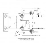
Won’t work, sorry. The 2,8 Volt bias will drive your tube in grid current. You need negative bias on the cathode-grid
thank you for your answers. Tube Cad unbalancer is nice, but only single ended. i ran a spice simulation and all went smooth. also there is a guide: Hi-End DAC tube output stage
in the guide output stage has been built and worked fine. i think i am missing something
in the guide output stage has been built and worked fine. i think i am missing something
In this case, there is a DC component + 2.8V that you must not bring to the tube grids. Insulation capacitors need to be added between the DDDAC and the grille so it will work.
Won’t work, sorry. The 2,8 Volt bias will drive your tube in grid current. You need negative bias on the cathode-grid
Actually the diagram given will work due to the current source Jfet
being powered from -12v. The cathode voltages of the differential tube pair will adjust accordingly to bias the tube with +2.8v on the grid. This is an advantage of the diff pair amp for this application. If you choose a tube and a current that allows for say-2volts of bias voltage then the cathodes would be at +4.8v and you may actually get away with using a low drop out voltage CCS part such as an LM334 in this application, thus doing away with the need for a negative supply.
I believe John Broskie uses this topology in the first stage of one of his 2 “Unbalancer” circuits.
negative supply is not an issue as 12AU7 heater also needs 12.6VDC, or in this case -12.6VDC. so i have negative supply anyway
Won’t work, sorry. The 2,8 Volt bias will drive your tube in grid current. You need negative bias on the cathode-grid
Actually the diagram given will work due to the current source Jfet
being powered from -12v. The cathode voltages of the differential tube pair will adjust accordingly to bias the tube with +2.8v on the grid. This is an advantage of the diff pair amp for this application. If you choose a tube and a current that allows for say-2volts of bias voltage then the cathodes would be at +4.8v and you may actually get away with using a low drop out voltage CCS part such as an LM334 in this application, thus doing away with the need for a negative supply.
I believe John Broskie uses this topology in the first stage of one of his 2 “Unbalancer” circuits.
ThAnks BFPCA
you are right of course, I missed the negative voltage 😱
Worth a try if you have all that stuff lying around for sure.
If not, Nixie is right, An excellent tube stage is normally pretty expensive !
you are right of course, I missed the negative voltage 😱
Worth a try if you have all that stuff lying around for sure.
If not, Nixie is right, An excellent tube stage is normally pretty expensive !
I have thought about a buffer for my DDDAC several times over the last couple of years. I always come back to the fact that the DAC even in single board form has a high enough output voltage and a low enough output impedance to not need a buffer for my situation.
I have decided that for my needs I would be better off to build a tube preamp and be able to have tubes in the system regardless of source. This is currently under way.
If you don’t like capacitors in the signal path you can always adjust out the small dc offset on the DDDac by fine tuning the output resistors and then put an input transformer in the preamp. Again, this could be used for all inputs. In my single board DAC the offset is only a few mv, so nulling it should be possible and it is very stable over time.
Other considerations: Putting tubes in the same box as the DAC will cause more heat and possibly hum if the power supplies for HV and filament are not in a separate enclosure. In my case I do not have the space in my DAC box or in my power supply box to include all the tube circuitry and power supplies, so the work and cost of doing a tube buffer is multiplied.
There are lots of possibilities for system configuration depending on your needs and preferences.
I have one more question. Output stage should draw about 10W per channel with 270V power supply, and output impedance is lower than 60ohms. As i mentioned this is an output stage so I don't need such low output impedance. I changed power supply to 150V (because it is shunt regulated) and changed the plate resistors (from 50k to 5k). The tube is at the same operating point with both power supplies (135V, 2.75mA). With 150V power consumption is about 2.5W and output impedance is 150ohms. Circuit is tested in multisim and works fine in theory. Do you think those changes are worth it? Isn't the plate resistor value too low? Any advice is appreciated. I attached 270V and 150V schematic
Attachments
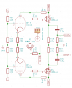
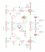
Again, I only took a quick look… 5k as anode load on an ECC83 seems terrible low to me.
Why use a tube with a MU of 100 and than squeeze the gain to by loading it with only 5 k ? The stage gain will now be like 5 to 8 x or so
I do not know why will follow this output amplifier. What output voltage do you actually need ? Where is this going to ?
I also wondered why you put the two 65 ohm in series as -6dB attenuator ?
i need 2V single ended output, so standard dac operation. this to me is a much cheaper alternative to output transformer. main reason of using tubes is a tube magic. i will be feeding this to a solid state headphone amp. two 65ohm resistor are current to voltage convereters for dac (2x65=130ohm). i use this voltage divider because i dont know how to decrease the gain of tube gain stage.
- Home
- Source & Line
- Digital Line Level
- A NOS 192/24 DAC with the PCM1794 (and WaveIO USB input)