Many thanks! It is pain stacking progress as us two are all having day job and family commitments! I seriously am missing this DAC...! Have few others, off the shelves DACs, are simply not the same flavoursome! 🙁Keep the photographs coming Chanh, it looks fantastic
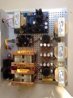
Here is the power-supplies at this point in time. Will make use of tomorrow (Saturday)for better progress.

Last edited:
Hello Chanh,
Being in the metal business for 25 years i would advice you to use some kind of reinforcement otherwise while lifting it you could put to much stress on the circuit boards and cause miniscule cracks in the tracks which could be very hard to find. Something in the shape of a metal picture frame and having the same hole pattern like the circuit board and connect that underneath the perforated panel using the four bolts in the corners and one half way in between them.
The hammond chokes dont buzz when you use them with choke input? Because they are so cheap and small ( compared to Lundahl) i wanna try and use them in my present dac too for 2 lower voltages needed in my circuit.
The tube part will be powered by tube rectifier, common mode choke input (Lundahl), another choke further down the line, maybe some black gates too because i still have these in abundance from a deleted project.
Greetings, Eduard
p.s Selectronic has 20% discount on all r core for one or two days more
Attachments
My DDDAC is complete!
Dear All
I posted a while back, when it was still a work in progress. Now I have completed my DDDAC (actually a couple of months ago, so I can be sure the components have all settled down).
It's just a basic 2 board DDDAC, as per Doede's and Lucian's designs, except for the following tweaks:
- Output stage tweaks: Cinemag transformers rather than caps, resistors replaced with Audio Notes. (Tried adding the optional HF filter caps (MKP4 10nF), but it sounded worse, so removed them - the Cinemags probably do sufficient HF filtering anyway.)
- S/PDIF input stage tweaks: added input transformer to coaxial input, and added optical input, with switching via relay. (Both optical input board and relay are powered by existing 12V supply.)
It really sounds rather good. (That's British understatement, by the way.)
All thoughts of further DAC changing are gone. Now I'm just enjoying the music. Thanks to all for the design work and help!
Kind regards
- Garry
Many thanks for your interests Guys! will post more photos in due course. From what I've seen today, I'm overly impressed. All credits to my good friend, who is extremely kind with diligence and attention to detail in assisting me with this works. It is beyond what I have hoped for from my personal's DIY perspective.
He is currently finalising both back and front panels' layout for the CNC process to kick start. A capacitor board will also be custom made to suit current Power-supplies layout. No messy wiring..! Going to be interesting..!
@Edward - many thanks for your tips in structural reinforcement! As Structural Engineer, that was my second nature! 😉 In regards to your query, these Hammond chokes are fantastic! Dead quiet (no hiss or whatsoever) as choke in put. Actually it performs better than my much costly copper chokes. The only disadvantage is they are 2A max. Therefore, I use them as second choke and using those 5A as choke input! The price I paid for each was US$28 each, so I cleaned them out! 😀
Hope to keep you guys posted soon.
Chanh
Last edited:
Hello Chanh,
The lundahl chokes are very good BUT they are to big to use them in all spots where i want to use a choke. SO i just use one for the tube stage in my dac. It is 64 Henry. I can use this value because the current including bleeding current is around 50 mA. 50mA also allows the use of a tube rectifier.
All the other voltages i need are below 20 volts and current below 200mA so choke input can be possible using the Hammond chokes because they offer a lot of choice and did find an addres in europe with lower prices than the ones in Canada.
One transformer is used to make +15 volt and -18 volts by using RC network to adjust output which is fed into solid state regulator. So i can do this too with choosing input chokes with different serie resistance and maybe a small rc network to do '' fine tuning ''
Of course have to get a small new power transformer. A so called split bobbin for 115 volts because the rest are 115 primary too. The original one is 2*14 volts with choke input it will end up 2*18 or even 2*24 volts. Will do some test with parts lying around before ordering.
Of course modifications have to be done step by step.
The transformer and the 2 chokes will take maximum 100$ so peanuts compared to the dddacc.
After that some resistor replacement in the actual circuit i guess well below 100$
Cap replacement? Have loads of them so no expenses here.
Hope the new boards will arrive soon so i will have something to compare lol.
greetings Eduard.
P.s Chanh you can use rubber gromets? to mount the circuit boards so that there will be no deformation of the board while the chassis is lifted.
Dear All
I posted a while back, when it was still a work in progress. Now I have completed my DDDAC (actually a couple of months ago, so I can be sure the components have all settled down).
It's just a basic 2 board DDDAC, as per Doede's and Lucian's designs, except for the following tweaks:
- Output stage tweaks: Cinemag transformers rather than caps, resistors replaced with Audio Notes. (Tried adding the optional HF filter caps (MKP4 10nF), but it sounded worse, so removed them - the Cinemags probably do sufficient HF filtering anyway.)
- S/PDIF input stage tweaks: added input transformer to coaxial input, and added optical input, with switching via relay. (Both optical input board and relay are powered by existing 12V supply.)
It really sounds rather good. (That's British understatement, by the way.)
All thoughts of further DAC changing are gone. Now I'm just enjoying the music. Thanks to all for the design work and help!
Kind regards
- Garry
Great news on your dac build. Did you find the input transformer on the coax input gave a good improvement? I'm thinking of doing the same. What transformer did you use if you don't mind me asking.
Cheers, Si
It's just a basic 2 board DDDAC, as per Doede's and Lucian's designs, except for the following tweaks:
- Output stage tweaks: Cinemag transformers rather than caps, resistors replaced with Audio Notes. (Tried adding the optional HF filter caps (MKP4 10nF), but it sounded worse, so removed them - the Cinemags probably do sufficient HF filtering anyway.)
It really sounds rather good. (That's British understatement, by the way.)
All thoughts of further DAC changing are gone. Now I'm just enjoying the music. Thanks to all for the design work and help!
Kind regards
- Garry
Hi Garry,
Congratulations on finishing your DAC. I am considering a very similar build.
I gather that you find the dual boards drive the Cinemags without any issue?
Did you use the standard Doede power supplies?
Cheers, Bryce.
Hi Garry,
Congratulations on finishing your DAC. I am considering a very similar build.
I gather that you find the dual boards drive the Cinemags without any issue?
Did you use the standard Doede power supplies?
Cheers, Bryce.
Yes, on both counts.
Cinemags sound great - a fuller sound than the standard caps, possibly just slightly less detailed, but overall more natural sounding and suiting my tastes and system (Naim amps + Royd Minstrel speakers). I think the Audio Note resistors also helped the output stage sound so good, but the biggest improvement was from the Cinemags.
Totally standard power supplies (bought assembled from the DDDAC web shop in fact).
Incidentally, I suggest experimenting with which Cinemag leads should be earthed - some say leave both white (case shield) and black (output winding shield???) disconnected, others say earth both. After trying various combinations, I actually preferred the sound when earthing white but leaving black disconnected.
I'm in awe of what the hard-core tweakers on this forum can achieve. However, my relatively standard DDDAC is by far the best DAC I've ever tried, which suggests that Doede's and Lucian's designs are excellent as they are. The one caveat is that I think that the standard output caps are just a kind of 'get-you-started' component, so strongly recommend Cinemags or some other output stage upgrade.
Kind regards
- Garry
Great news on your dac build. Did you find the input transformer on the coax input gave a good improvement? I'm thinking of doing the same. What transformer did you use if you don't mind me asking.
Cheers, Si
Hi Si,
No audible improvement from the input transformer, sadly, but there was never anything wrong with the coaxial input to start with, to be fair. I only did it because
(a) I know a lot of coaxial outputs, like that on my Squeezebox Touch, have no isolator on the S/PDIF output, and I have read that these connections SHOULD have an isolator.
(b) I now have electrical isolation on output (due to Cinemags) and all other digital signal inputs, so I thought it would be good to be completely isolated.
In fact my coaxial input now only goes up to 96 KHz before distortion kicks in. I used to get 192 KHz. The drop isn't necessarily to do with the input transformer, although it might be. I have also added relay switching between coaxial and Toslink inputs, which could be to blame. Or could be a bit of both.
If I haven't put you off (!), the input transformer component is Murata DA101C. I got it from Farnell.
Kind regards
- Garry
DDDAC1543 with 60 chips
...well, alright, although it is not a DDDAC1794 but a DDDAC1543 with 60 chips running in one of the very best systems on the globe with all highest end Goto drivers, in Japan, where I have been recently with Jean Hiraga (he and me running a DDDAC1543 with 120 chips each as well) and others, a hint for your pleasure and inspiration where another discussion of the DDDAC1794 is running for years might be allowed:
DDDAC 1794-NOS 24-192
Reply #400 (if you should want to read more, then go before...)
enjoy...
Hi Reinhard, Some facinating adventures you've been having in Japan with a lot of good food and music by the looks of it. 🙂
Thanks for being a gentleman about the copied content, better to link to the source so those intrested get the full context.
I can't post on the Killerdac forum because the administrators have still not approved my account..
Thanks for being a gentleman about the copied content, better to link to the source so those intrested get the full context.
I can't post on the Killerdac forum because the administrators have still not approved my account..
Is this going to work?
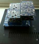
Hi all, my DDAC kit arrived 🙂 and I've been busy getting the case design figured out and collecting the other bits and pieces I need. I would appreciate your views and advice regarding the configuration in my photo. This is a 4 stack DDDAC with two of the boards upside down, the edges carrying bits are lined up - the edges with analogue are separate, but will be connected together of course. The reason for doing this is to fit a 4 stack DDDAC into a 2U case. I can use 10mm spacers as shown which actually gives 22mm between boards (as they alternate) - so if I decide to fit shunt regulators I have a bit more room for them.
Is there any reason you guys can see that this wouldn't work, or is a bad idea for some reason?
(answers regarding the music coming out upside down will be given due consideration!!!)
Attachments
...well, alright, although it is not a DDDAC1794 but a DDDAC1543 with 60 chips running in one of the very best systems on the globe with all highest end Goto drivers, in Japan, where I have been recently with Jean Hiraga (he and me running a DDDAC1543 with 120 chips each as well) and others, a hint for your pleasure and inspiration where another discussion of the DDDAC1794 is running for years might be allowed:
DDDAC 1794-NOS 24-192
Reply #400 (if you should want to read more, then go before...)
enjoy...
There are no words to explain my feelings to what a wonderfull advanture you presented in such a perfectly involving manner! One can only dream of it. Obviously there is a long way to go to make it come truth. It must be so much rewarding and educative for you. All great people gathered together sharing all their inimaginable achievments of the lives that take your breath away. Incredible what people can do!
Big thank you rhlauranna for taking us in that beautifull "virtual" trip in your small group company, and for leting us to encounter biggest people of Japan and for presenting a little of a neverending Japan's heritage.
This has brought a lot of inspiration, no doubt!
PS.
This part looks interesting at the bottom: DDDAC 1794-NOS 24-192
Looks like something new to be tested! 🙂
Last edited:
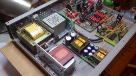
Update on DDDAC's power supplies!
Hey guys!
After some spare hours during the weekend, my friend "Don" had came up with a PCB for the caps and he is getting closer to finalise the below deck compartment of raw unregulated power supplies for DAC and BBB.
Next up will be CNC for front and rear panels!
Hey guys!
After some spare hours during the weekend, my friend "Don" had came up with a PCB for the caps and he is getting closer to finalise the below deck compartment of raw unregulated power supplies for DAC and BBB.
Next up will be CNC for front and rear panels!
Attachments
I have some spare DDDAC parts going spare so I have put them on Ebay.
1 off red motherboard with Audio Note 33R 2w Tantalum resistors for IV conversion.
1 off SPDIF to I2s board, and 4 off Shinkoh 16R 2w Tantalum resistors for IV conversion with 8 Dac boards.
1 off red motherboard with Audio Note 33R 2w Tantalum resistors for IV conversion.
1 off SPDIF to I2s board, and 4 off Shinkoh 16R 2w Tantalum resistors for IV conversion with 8 Dac boards.
I have just placed my order for another 5 Dac boards, so when they arrive I will be able to find out if the new SPDIF motherboard will support a total of 16 Dack stacks 🙂
- Home
- Source & Line
- Digital Line Level
- A NOS 192/24 DAC with the PCM1794 (and WaveIO USB input)