'I'll stick with proper circuits from now on.'
If the above means Eli's circuit is not proper then we assure you that it's a complete and proper/correct circuit.
We salute you for the effort you put into the build. Pls try again. Put PS circuit to one side of the box and signal circuit to another. Keep input and output wires away from power supply. Twist heater wires as much as possible and keep it close to the box surface. Keep the tubes away from PT and Chokes. Double check your volume pot wiring.....you will be successful at the end if you try hard and that will give you immence
pleasure.
Many diyers tried Eli's 12b4 circuit and it's a wonderful pre with proper gain for line drive. Wish you success in nearest future.
Regards
Please check the value of the 1.5M resistor with a DMM. You need to de-solder one end of the resistor for proper measurement. Very low value may eat-up gain. Also check the value of the input resistor i.e. tube grid to ground. Please remember tube pins/socket pins are read from downside. PLEASE TRY AGAIN, you will be successful this time.
Regards
Regards
Thanks for your encouragement minhaj. OK I'll do it again . We read the tube pins looking at the base so from underneath if it were in place , right? Number 1 is to the left of the gap , with the gap at the top, yes?
Those values of the 500ohm to the gate and the 1.5M are correct.
So I'll get a different breadboard and rebuild the circuit as you suggest.
Cheers.
Those values of the 500ohm to the gate and the 1.5M are correct.
So I'll get a different breadboard and rebuild the circuit as you suggest.
Cheers.
I am very happy that you agree to try again. Hold on, I am at work now, I will come back to you in an hour.
Regards
Regards
Vacuum Tube Pinouts
12B4A @ The Valve Museum
Please print the docs, read these carefully and keep it handy. Don't rush, rather knowledge first, choke down build plan and proceed slowly. Until you succeed we won't let you loose.
Regards
Regards
12B4A @ The Valve Museum
Please print the docs, read these carefully and keep it handy. Don't rush, rather knowledge first, choke down build plan and proceed slowly. Until you succeed we won't let you loose.
Regards
Regards
DIY Paradise
Study time, please check above link and study how the 5687 pre is built. 5687 is a twin triode but it will give you a clear idea how to build tube pre.
Regards
Study time, please check above link and study how the 5687 pre is built. 5687 is a twin triode but it will give you a clear idea how to build tube pre.
Regards
Once you are ready after going through the above, please tell me so and we will dive into build phase.
Regards
Regards
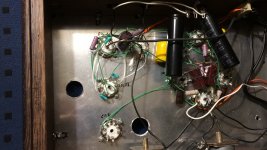
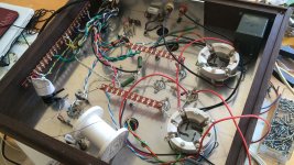
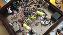
Rebuilt much neater. Took it all onboard. Made a separate signal board from the PS.
Still a fail. Plug amp into output and there's a slight hum. Plug input in from the computer and it screams. Not even remotely working.
I think I may have fried the IOM45's as when I first started I had a couple of shorts from the valve terminals which tripped the circuit breaker. This happened about 5 times till I finally tracked down the culprit. There doesn't seem to be any voltage from the IOM45 terminals going into the valve. I thought that should be measurable.
Any hints to check those things?
Request you to replace the Plate CCS with a 6k-8k 10W resistor and try. Plate voltage (from plate to ground) should be 90-100 volt and cathode voltage (from cathode to ground) should be 5-6 volt. Heater voltage across heater pins should be 6.3 volt. If these are ok but no sound the something wrong with input and/or output. Do you read voltage at PS out?
Regards
Regards
Please read:
cathode voltage (from cathode to ground) should be 9-10 volt
instead of
cathode voltage (from cathode to ground) should be 5-6 volt
Regards
cathode voltage (from cathode to ground) should be 9-10 volt
instead of
cathode voltage (from cathode to ground) should be 5-6 volt
Regards
I don't understand what Plate CCS means sorry. Are you talking about the 1.5M resistor?Request you to replace the Plate CCS with a 6k-8k 10W resistor and try. Plate voltage (from plate to ground) should be 90-100 volt and cathode voltage (from cathode to ground) should be 5-6 volt. Heater voltage across heater pins should be 6.3 volt. If these are ok but no sound the something wrong with input and/or output. Do you read voltage at PS out?
Regards
I have discovered the following voltages. Firstly across the heater terminals there is 13 volts, not 6.3V.
Plate -ground is 13.7
Cathode -ground is 8.2
PS after the IOM45 is 13.1.
I discovered this morning that the negative from the power supply was not connected so I was very hopeful that this major omission would be the answer but it was not to be.
The initial power at the zener diode has 120V AC and this becomes a bit over 400V DC at the beginning of the circuit. The IOM45 then regulates that down to 13.1 which is impressive. I have them mounted straight onto the heavy aluminium base of the cabinet but I wonder if they should have their own dedicated heatsinks?
I am also confused about the ground connections for input and output.
Should all the grounds be common with the earth on the signal board which is the common earth for the power supply? I would have thought so.
As someone said with the questions I ask I probably shouldn't even attempt this stuff. But perhaps with your tuition minhaj I will come through to the other side. Thanks so far but I will accept your decision if you decide I am a basket case.
Cheers.
At one point of time everybody was a basket case. No issue at all.
Let us start.
plate CCC is constant current source for the plate (10M45 not IOM45).
12B4A pin arrangement are as follows:
1 2 3 4 5 6 7 8 9
Cathode Grid Heater CT Heater Heater NC Grid NC Plate
I think your 10M45 is fried you replace that with 6k-8k 10 watt resistor. It will be in-between B+ and plate/pin no 9. 500 ohms resistor will be in-between cathode/pin no1 and ground. Solder each 2.2k resistor to grid/pin no 2 and 7. Solder a short wire in-between open ends of 2.2k resistors. Connect your input wire to 2.2k shorted end.
Heater wiring: If your heater winding/supply voltage is 6.3 volt
Solder a short wire in-between pin 4 and 5. Now connect you 6.3 volt supply to pin 3 and 4. You are done.
Output wiring: Solder your output film cap to plate/pin no 9- other end to output socket pin. 1.5M resistor should be connected in-between output pin and ground.
'Should all the grounds be common with the earth on the signal board which is the common earth for the power supply?' -there are more to it but for now it is 'YES".
'The initial power at the zener diode has 120V AC' -these are rectifier diodes.
IF YOU CAN LEARN HOW to OPERATE A COMPUTER THEN YOU CAN LEARN TO build a TUBE PRE NO QUESTION ASKED.
Regards
Pin No
1 Cathode
2 Grid
3 Heater Center tap
4 Heater
5 Heater
6 No Connection
7 Grid
8 No Connection
9 Plate/Anod
You will have to be successful very soon. Because I plan to move into my next project together.
Regards
1 Cathode
2 Grid
3 Heater Center tap
4 Heater
5 Heater
6 No Connection
7 Grid
8 No Connection
9 Plate/Anod
You will have to be successful very soon. Because I plan to move into my next project together.
Regards
@Wot: after more than 2 years it might be OK to reread post #6. Don't be surprised to discover you could have used a source selector and a volume control for the Aleph-J. Aleph-J has an input impedance of 242k and input sensitivity of 1.5V rms. Any modern source can drive that without any added electronics/distortion/extra connectors + cables/added noise/ lost hours.
A metal box connected to PE, a good source selector (or a PCB with relays) and a very good volume control of let's say 25kOhm to 50 kOhm, 2 x 4.7 µF film caps top protect Aleph-J from sources with DC offset and you are done. It would be even better to add all these components IN the Aleph-J.
A metal box connected to PE, a good source selector (or a PCB with relays) and a very good volume control of let's say 25kOhm to 50 kOhm, 2 x 4.7 µF film caps top protect Aleph-J from sources with DC offset and you are done. It would be even better to add all these components IN the Aleph-J.
Last edited:
Jean-paul, you are quite correct in some ways.
Though I've never bothered to install a volume control in the Aleph I have used it with my turntable and a small preamp, but mostly I have it plugged in to my laptop and play my vast digital music collection using VLC media player which has it's own equalizer that works very well for my workshop sound.
The idea of the valve preamp was to play with the input sound and hopefully to add a clean[ish] but valve flavoured input which would possibly be great for when I return to the Linn Sondek and the vinyl. I use a hybrid Monoprice in the house at the moment which is a valve preamp and a 25watt per side solid state output. It's quite nice but not a patch on the Aleph of course.
The house sound project involves a room that I have built with a pantry to one side, in which I will house an Aleph J and a pair of folded transmission line units that I'm building with a pair of Falcon acoustics B139 replicas for the bottom end that will protrude through the wall and then a pair of AMW bookshelf speakers that will be mounted on bookshelves in the main room. I don't know if I'll like the tube preamp but I wanted to give it a try. So I don't think I'll alter the Aleph box just yet. I have also ordered a crossover unit from the DIY shop as well as a preamp[Wayne's burning preamp] and power supply so there will be options. For the digital stuff I'm starting to use a Raspberry Pi with it's own preamp and small screen that I have yet to get. That way I can avoid using a laptop or a desktop for driving any of my hard disks. [If it sounds any good.]
Minhaj,
Thanks again for your persistance with me. OK so I think I've worked out why it doesn't work. It's kind of embarrassing. I haven't got enough stuff earthed. I think it's going to be that simple. I don't think the 10M45's are fried because I get a straight 13 volts from their output .
However I do have a problem with the heater circuit because it is 13 volts for each side , not 6.3 volts as the specs and you suggest. I'm wondering if this will really matter in the scheme of things since these valves seem to be robust and have varying capacities for taking different volts. But I think it might add distortion and certainly seems to increase the other voltages that you mentioned.
So if you think it is essential to have 6.3 V on each heater I'll need another transformer , as I bought the one that Eli recommended. It's 24V Series and 12V parallel. That is unless there's an easy way to halve the output volts.
But tomorrow I plan to rush round with some decent earth wires everywhere and test it once again . The way it is it can't possibly work. I've looked at it all afternoon and was just waiting for your confirmation. I'll run them all onto the chassis.
You see it's the noob thing that seasoned people don't even think about any more and therefore forget to mention it in the drawings. I think that's what I mean by a 'proper' circuit. One that describes the whole thing and leaves nothing to the imagination of the novice.
I know. Just as that adding GAIN (in capitals as it can't be high enough) to anything that specifically does not need gain is an incurable habit amongst many of the tube guild. If they could add it to their coffee machines they would do it. It does have a function though, it creates issues which need to be solved so there is always something to do.
If sources are low Zout and amplifiers have enough gain and high Zin then anything in between is superfluous unless one wants to add a function generator that adds tons of gain, has the amplifier blowing the windows with volume at 9 o'clock position, does strange things with the previously undistorted signal, amplifies noise (and adds its own noise for free!) and distortion.
Since some 40 years when CD was introduced no preamp is needed anymore when adhering to standards, just source selection and volume control are then needed. Standards yes, so no self created one off situation in every home and thus signal levels that are the same with almost every source device since then. I think that was a very good idea as any source can be connected and it will always work without any hassle and without volume differences when switching sources. What a great invention.
If there is a desperate need to add something then only a buffer or very low gain preamp in whatever form makes sense. It should then also have relatively high Zin and low Zout (lower than the sources otherwise results are backwards). Only exception is antique devices but upgrading their output level is more efficient than adding gain to devices that don't need it. The Raspberry Pi also does not need any preamp if it has a DAC HAT as DACs are 2Vrms output.
In short: forget about preamps with GAIN. And if the need to do something is too strong always compare what is added with a straight wire and listen what satisfies best.
PS: if you use the Aleph-J with a laptop and rely on software volume control there is the risk that when something goes wrong (always when you are in the kitchen making a coffee or when you're in the shower) your speakers will burn. Any amplifier should have volume control as minimum protection. An "open" power amplifier will eh... amplify anything that comes at its inputs with its defined gain. So if things go wrong at the software side of things then there will be noises/sounds but no smoke. Secondly is hardware volume control in most cases way better for signal/sound quality than software volume control.... Contradictory as it may seem is this the odd situation where a XXXXXX would have the function to limit volume of the source that lacks hardware volume control.
Last edited:
The DAC HAT is what I refer to as a preamp. I think it does give a boost which is needed because the straight Pi output is too low for music. It's fine for watching movies with the amp volume flatout but music needs to be working with the amp set lower or it does distort and it isn't loud enough.
Pirate Audio: Line-out for Raspberry Pi – Pimoroni
I don't quite understand all your specs.
Now I've read about the Wayne preamp and it appears to be used with Aleph J amps with some glowing reviews. Are you denying the validity of that?
But although I may agree with you once I've been through this exercise I still want to hear it in it's working form. Thanks for your opinions.
If the valve preamp turns out as you predict I may use it for an antique project that I have waiting for me. It's an old HMV record player, lowfi, mono, that my parents got when I was about 1yo. So it's a 1954 jobbie, with a hideous garard turntable and heavy saphire stylus, strange oval speakers mounted in a heavy solid wooden cabinet. The amp has 12AX7 etc. I forget but despite cap replacement it still crackles so it's going to get new valve sockets. Then I'll build a replica and make it a stereo and probably couple it with this preamp if I can get it happening. It has a beautiful sound when old scratched records are used. Seems to filter the scratches somehow.
No doubt from what you have said you would cringe at the mention of such archaic nonsense but I have nostalgia for it and other people have been impressed when it was working right. My intended mods are maybe just looking for something to do but may have other benefits . I'll post about it when it happens.
Don't get me wrong, I appreciate your cynicism.
Hi I see it as realism 🙂
The Pi output may be too low but with a HAT it should be the standard of 2V rms output normally as 99% of source devices. Glowing reviews are used to pack the potato peels in 😀 as anything very good that is superfluous still is superfluous. Not many electronics win from a straight wire when all necessary conditions are met. When things are designed and built according some simple standards with regards to signal levels, input- and output impedances and enough gain of the power amplifier they will work automatically together. Boring as it will just work and sound good. Adding something extra won't make things better then (in general).
Nothing wrong with archaic stuff but Aleph-J is not archaic, RPI with HAT is not archaic etc. The mixing of very old and modern might give some issues. A very long time ago signal levels were low, very low and one needed a lot of gain to make it workable. Now not so much. So when coupling very old stuff with very low signal levels to more recent devices it is efficient to have their signal levels upped and not of all sources. It saves for shock moments as well when switching sources. When this phenomenon is noticed one just knows things are off. Contrary to what you might think I really like well designed old stuff (or new stuff designed with old parts) but then making devices perform the best way they can in a modern setup is rewarding.
There, I see a challenge! 🙂 We could look at devices as building blocks just like it are plugs and sockets that need to be of the same family to fit and work optimally.
The Pi output may be too low but with a HAT it should be the standard of 2V rms output normally as 99% of source devices. Glowing reviews are used to pack the potato peels in 😀 as anything very good that is superfluous still is superfluous. Not many electronics win from a straight wire when all necessary conditions are met. When things are designed and built according some simple standards with regards to signal levels, input- and output impedances and enough gain of the power amplifier they will work automatically together. Boring as it will just work and sound good. Adding something extra won't make things better then (in general).
Nothing wrong with archaic stuff but Aleph-J is not archaic, RPI with HAT is not archaic etc. The mixing of very old and modern might give some issues. A very long time ago signal levels were low, very low and one needed a lot of gain to make it workable. Now not so much. So when coupling very old stuff with very low signal levels to more recent devices it is efficient to have their signal levels upped and not of all sources. It saves for shock moments as well when switching sources. When this phenomenon is noticed one just knows things are off. Contrary to what you might think I really like well designed old stuff (or new stuff designed with old parts) but then making devices perform the best way they can in a modern setup is rewarding.
I don't quite understand all your specs.
There, I see a challenge! 🙂 We could look at devices as building blocks just like it are plugs and sockets that need to be of the same family to fit and work optimally.
Last edited:
- Home
- Amplifiers
- Tubes / Valves
- A Noob Valve Preamp Build?