Thanks Bigun,
That's very interesting. I'll have a go at that theory. I just spent all day struggling over a crackling amp. The HMV. It has an intermittent crackle which I've been seriously chasing. It's almost like a cap loading and discharging somewhere. First I recapped it almost completely, save for a couple of pF caps, 100pF and 5000pF because the replacements I got were not adequate . However I have eliminated them as cause by disconnecting and still hearing the crackle. I replaced the power tubes which were 6M5 and I fitted 6CK6 instead with the only alteration being to bridge pin 3 with pin 6, the 6 not being used in the 6M5. Anyway I found the 6CK6 a little more harsh but still had the crackle.
I found the shielded inlet line was old and horrible with disintegrating insulation but replacement didn't help. I replaced the volume pot, again no change. I cleaned every pin of every valve and went round with a hot iron on any join that didn't look good. Then as I listened the crackle disappeared like the volume of it was turned down and I had silence. Then half an hour later it came back. The thing sounds amazing playing records despite the crackle. I'll replace the other two pots next though they don't crackle when adjusted. Crackle happens without the turntable input connected, also with the tone tube removed and even with the phase splitter 12AX7 pulled out. At one stage a wire fell off the input plug and when soldered back the crackle left but then returned. There isn't much left apart from the transformers and the rectifier tube. There are three speakers which have been pulled out one at a time so eliminated them. Still it uses one of those horrible old 4 pin plugs to the speakers so maybe fit modern plugs. Also disconnected the on off switch that runs off the back of the treble pot, eliminated as cause. There again it could do with a modern power inlet with fuse.
I also began to wonder about the old valve sockets as those must get nasty in their old age. The amp was new in 1952. Anyway I think it will be a very nice exercise to build two copies of this unit with all new bits though not sure what speakers will suit then. It could be laid out much neater too.
Member
Joined 2009
Paid Member
There isn't much left apart from the transformers and the rectifier tube.
Perhaps insulation breakdown inside the output transformer?
Yes that's one advantage of deciding to clone it, if I buy a replacement that isn't needed it can go in the next one. I got twice the numbers of caps for that reason. Trouble was I ordered tiny little resistors that I can hardly see so back to the order board. I just need to measure the actual output of this one now so I can find an equivalent. How do you not buy unnecessary parts occasionally? I'm doing it on purpose so I'll have a few spares here and there. I'm gathering the makings for another Aleph J because I know somebody is going to want mine when they hear it.
I now have the parts and a bit of time to think about this. I just can't decide how to hook up the current controller. Here's the diagram. There are no open ends so I'd be guessing I'm afraid.

Boot.
Talking about the 12B4 preamp, I am wondering how to hook up the current controller .
I now have the parts and a bit of time to think about this. I just can't decide how to hook up the current controller. Here's the diagram. There are no open ends so I'd be guessing I'm afraid.
Boot.
Talking about the 12B4 preamp, I am wondering how to hook up the current controller .
The anode goes to B+. The gate/resistor junction connects to the 12B4 plate. The entire CCS group is the plate load.
Very important, did you size the 10M45S' cathode resistor according to the part's data sheet?
Very important, did you size the 10M45S' cathode resistor according to the part's data sheet?
Yes according to the graph I should get 20milliamps using a 150K resistor.
So if I understand you right I take a lead from the 'G' terminal on the mosfet down to terminal 9 on the 12B4 and from the 'A' terminal it goes to B+ as well as from the main power, so a junction there as well.
So if I understand you right I take a lead from the 'G' terminal on the mosfet down to terminal 9 on the 12B4 and from the 'A' terminal it goes to B+ as well as from the main power, so a junction there as well.
Yes according to the graph I should get 20milliamps using a 150K resistor.
Should be 150 ohms I believe.
Should be 150 ohms I believe.
I hope you are wrong. The chart shows Series Resistor R K ohms so that's why I chose 150K ohms.
Here's the link to the data sheet.
Last edited:
RK is what they have labeled the resistor. It's not kilo-ohms. The chart shows a variation of 10 ohms to 10000 ohms.
I read it as 10K to 10000K ohms since below it says Resistor Rk-ohms.
Am I right or wrong? I stand for correction..
Am I right or wrong? I stand for correction..
Check figure 1 right above the chart. Rk is referencing the resistor that goes in that spot. Its not referencing the the ohm of it. Maybe somebody could clarify this more clearly than I can.
So why would it have a K below the Ohms R?
If that isn't sposed to be K Ohms I am totally confused. Well more totally confused.
If that isn't sposed to be K Ohms I am totally confused. Well more totally confused.
Since the pins are labeled A, G and K I imagine its a reference to Kathode (meaning the resistor in the Kathode spot)which usually means the negative connection. A is anode which is the positive connection, and G is grid. Google 10m45s ccs and you'll see that the resistor in that spot is rarely over 1000 ohms. Most are in the 100 to 500 ohm range. I'm sure someone else will chime in about this, that's the beauty of Diyaudio.
https://www.audioxpress.com/assets/upload/files/Sources_101_P2.pdf
Check out figure 12a for circuit set for 30 milliamps.
https://www.audioxpress.com/assets/upload/files/Sources_101_P2.pdf
Check out figure 12a for circuit set for 30 milliamps.
OK thanks Brik, I'm convinced and slightly less confused. 150ohms it is. Damn I haven't got one here. Maybe Jaycar will have them.
Appreciate your help.
Appreciate your help.
There is a slight variation between individual mosfets . One mosfet might give 20 milliamps with a 125 ohm resistor,another might give 20 milliamps with a 175 ohm resistor.Close is good enough.
Good luck with it.
Good luck with it.
I wonder if a trimpot might be better there.
Anyway I've drawn a kind of layout/schematic to begin with. Can you see any glaring mistakes?

Anyway I've drawn a kind of layout/schematic to begin with. Can you see any glaring mistakes?

Everything looks good. Might want to add a stopper(the 1k in the pic) resistor to the G input on the Mosfet for added stability, also a small poly bypass cap (.1 to .47 uf) on the B+ nearby the mosfet,also for added stability. I hope George doesn't mind me using his powerdrive schematic to help you out. 🙂
Thanks Brik I'll do what you suggest. Does this reduce ripple or have any other audible effect?
The stopper resistor and the local decoupling capacitor are basically to insure the circuit remains stable.Mosfets can be temperamental at times and oscillate if care is not used with their layouts.
So WOT, we are left wondering if you ever finished your 12B4A amp or fail to complete as BIGUN predicted. I personally hope you finished it and that you have some final pics to share and your impressions of the amp.
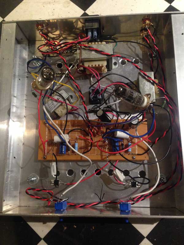
Finally I pulled the box of parts out of the cupboard a few days ago and built this project.
Many things have got in the way of electronics for me since 2018 when I hassled Eli unmercifully for this circuit.
I had purchased the choke and the two transformers and a pair of 12B4 secondhand valves as well as the IOM45 voltage regs with the 150ohm resistor.
I didn't have the extra stuff that Brik suggested.
I made up a heavy duty aluminium box that is partly riveted and partly screwed together.
I began with a point to point theory but abandoned that for a crude bread board layout that I managed to nut out for the circuit.
It's a bit messy but I've turned it on and nothing exploded or burned and voltages were correct at various places.
So I couldn't wait till tomorrow to hook it up.
However it makes a nasty buzz and sucks the sound out of the Aleph so I turned it off quick and it is pronounced a fail. I don't know enough or have the patience to attempt to make it work. Should have left it in the drawer or never even tried . But I did try and now it's out of my system. I'll stick with proper circuits from now on.
It's probably no wonder it doesn't work cause I was exceedingly messy with the build . Just for the perfectionists I'll show you all my small disaster. Sorry, I can build something that's properly laid out like the Aleph but this thing allowed extrapolations in many directions and I was way too slapdash.
I know I could improve it just by using shielded cable for the input and output but I fear it also needs a completely better layout and even then I have my doubts that it works properly at all.
It wasn't just the hum, it actually severely reduced the output so there's obviously something seriously wrong with the whole thing.
But it was fun and that's the main thing and I learned never to try to use some half boiled circuit with no proper layout again. I'm way too ignorant electronically to even know where I probably went wrong. It could be anything or everything. That's the problem with such a project. To analyse it fully I would start from square 1 again.
I'd fit the transformers closer together and the rest further away and fit shielded cable but even then I think maybe I need new valves or a different value for the IOM45 thingo or different values for the final bridge of the power supply , the list is endless and I'm just shooting in the dark, which as a mechanic I know is the wrong way to diagnose anything. I call it a fail and move on..
- Home
- Amplifiers
- Tubes / Valves
- A Noob Valve Preamp Build?