Do you have a Jaycar nearby? They can do HV caps, cabinets etc. How do you feel about repurposing and testing iron to use as a choke?
Hear, hear, Wot. Well said !I finished an Aleph-J amp which had a pretty comprehensive build guide and didn't expect too much from the assembler in terms of in-depth calculations or even too many choices which allowed me and I suspect lots of others to build this amazing amp and many other amps.
I run it using a cheap Monoprice integrated amp which happens to have a line out from the valve preamp and I am pretty happy with the sound. However I would really like to make a good quality valve preamp[line stage] and even a phono one as well as mine is a tiny solid state Rega.
OK here's the thing. I have spent day after day reading through various preamp threads but I have not found one that documents the build completely in a way that makes it possible to just buy the parts and build it. Even the Aikido has so many choices that I was left confused and would need advice to choose the various components and still more advice to choose the specific transformers.
Every single thread goes into interminable arguments about all kinds of variants many of which are only measurable with pro equipment and the knowledge required exceeds my very newly acquired interest in this field. I could probably build from a schematic but then I get crossed wires about how many transformers are needed and all the talk of valve substitution and it goes on and on and on and the more I read in a thread the less inclined I am to get halfway into one of these projects only to find I can't get through it or fix too much hum or something.
So I'm actually begging for someone to do a full build guide for a 12B4 or something sweet and simple, including the whole process, power supply, BOM and layout whether or not there are circuit boards available, but using components that are easily purchased.
I believe something like this may be in the pipeline in the DIY shop which will then no doubt have an excellent build thread by 6L6 and we'll be able to join the ranks of the experts at least in being able to have this stuff to listen to.
But I'm putting this thread up here in the hope that some alternatives are already about that apply to this beginner level.
Cheers.
At this point I am attracted to Eli's design, I have the good schematic for the preamp and I have the correct transformers however I am not at my stage able to design or source a nice little well filtered power supply that fits.
Look at the "fancy" PSU. The bridge rectifier is pretty obvious. 4X of this Schottky diode will comprise the bridge. A candidate choke for a CLC (Π section) filter has already been mentioned. All that remains of the filter is capacitors. 2X of something like this gets things done.
A detail needs finessing. Notice that the 12B4 heaters are biased off B+. The "fancy" filter yields a lower B+ rail voltage than the CLC filter will. That gets dealt with by changing the 330 Kohm part in the voltage divider to 390 Kohms.
Amb a10: The α10 Stereo Pre-amplifier
SP9: Vacuum Tube Audio preamp kits
I like the Muchodumbre as well.
SP9: Vacuum Tube Audio preamp kits
I like the Muchodumbre as well.
Last edited:
Look at the "fancy" PSU. The bridge rectifier is pretty obvious. 4X of this Schottky diode will comprise the bridge. A candidate choke for a CLC (Π section) filter has already been mentioned. All that remains of the filter is capacitors. 2X of something like this gets things done.
A detail needs finessing. Notice that the 12B4 heaters are biased off B+. The "fancy" filter yields a lower B+ rail voltage than the CLC filter will. That gets dealt with by changing the 330 Kohm part in the voltage divider to 390 Kohms.
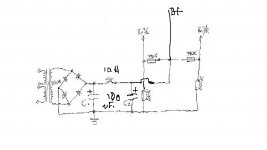
Alright so perhaps from what you say the power supply might look like this?

In which case C1 and C2 are 100uF 250V caps right?.
And though I understand a choke as a coil it must also have a value?
I would use a full bridge rectifier by preference to 4 separate diodes. Is that OK?
Last edited:
Fellow Australian here. What sort of budget are you working to? And are you finicky about final presentation, or just want to make something?
I ask as the supply of transformers down here is limited, and some creativity can be required.
At the risk of offending the purists, you can do heater's with a cheap transformer from jaycar/altronics (happy to point those out if required). For HV, you can back to back a pair of transformers (ie attach a second transformer to the firsts secondary that'll turn your low voltage back up to high), or find a mains isolation transformer. On all of those you can make it into wahtever voltage you like using <cough cough> solid state regulators.
I said "simple". Here it is.
Just to be clear, the parts values in the voltage dividers are 390 K and 680 K.
I previously linked candidate filter caps. and a candidate choke.
It's well filtered and the 10M45S CCSes will provide quite adequate PSRR.
Just to be clear, the parts values in the voltage dividers are 390 K and 680 K.
I previously linked candidate filter caps. and a candidate choke.
It's well filtered and the 10M45S CCSes will provide quite adequate PSRR.
Attachments
Member
Joined 2009
Paid Member
Did you look at these options? You get all the parts, schematic, etc, These are clones of proven famous designs and because of their fame they are popular so there are plenty of internet sites with more information. You can also modify/upgrade etc. e.g. Thorsten’s upgrades for the Ear phono. So you get to build it yourself with a good likelihood of positive results and learn more about the craft, a bit of history about the ‘greats’ all for some pretty good prices.
Last edited:
I have a clone Marantz 7 line stage preamp that i assemble from a kit, some 20 years ago.
It is still lying somewhere in storage, maybe its time to revive and enjoy it again.
I remember using top notch components and parts, and i paid a bomb for it.
Let me post some pics of the set, during the "revival" process.
Marantz 7 line circuit was very popular in Asia at that time, especially in Japan, HK, Malaysia and Singapore. Don't know if it still stood up the test of time till now. You may want to take a look into it as a preamp project.
I said "simple". Here it is.
Just to be clear, the parts values in the voltage dividers are 390 K and 680 K.
I previously linked candidate filter caps. and a candidate choke.
It's well filtered and the 10M45S CCSes will provide quite adequate PSRR.
By the 10M45S I assume you speak of the choke of which you recommended the Triad C-7X. Is this the one and does it matter which way round it is wired?
Thanks so much for descending to this level for me Eli. I think I just about have it wrapped up.
Notice the 2 interlocked circles in the signal circuitry schematic. That's the symbol for constant current
The 10M45S is a TO220 case constant current device. Here it's used as a plate load. Refer to the previously linked datasheet and work out the resistors needed to set the device up for 20 mA.
There is no particular configuration for the C-7X choke.
The 10M45S is a TO220 case constant current device. Here it's used as a plate load. Refer to the previously linked datasheet and work out the resistors needed to set the device up for 20 mA.
There is no particular configuration for the C-7X choke.
Thanks for all the suggestions. Now that I have cleared up everything in my mind with the 12B4 preamp I've made a shopping list and placed the order.
My BOM is as follows:
From Mouser:
Transformers: Triad N-68X and Triad VPL24-400
Choke : C-7X
Current Regulator : IOM45S, IXCP version x1
Resistors :
150K x2
390K x2
680K x2
100K x2[mistake should have been pots]
2.2K x4
500r x2
1.5M x2
Capacitors:
100uF 250V x2
33uF 500V x2
100uF 100V x2
3uF 100V x2
Potentiometers:
100K audio x2
Total cost $143Aud
Then I made an order to Antique Electronic Supply.
Anticipating that I will want to build the tone control that Eli showed us I got the valves for that too.
Valves :
12B4A x2
12AX7 x2
Sockets for 9 pin x4
Multi terminals assorted.
Total $110USD
So now for the long wait for the parts and meanwhile I'll work out the layout and the case.
Thanks so much to Eli Duttman for being so incredibly patient with me.
If it's OK with you Eli I'll document this build including a nicely drawn schematic and layout as an example of how a total Noob job with a lot of good help can make one of these. I hope I won't need much more now. I'll get you to finally check my schematic when it's drawn properly if you don't mind. It's your intellectual property in any case so will have your name on it.
This is what I had hoped to achieve to take the mystery out of a first valve project and make it easy to build for others like myself.
Edit, just realized I forgot the bridge rectifier but I have two already in my spares box.
Last edited:
Amend the AES order. Drop the 12AX7s, as you need 2 bottles per channel. Forget tone controls!
You need 2X 10M45S current sources. Each signal tube needs its own load.
Double check that you don't order unnecessary parts.
Carefully examine the power dissipated in resistors. Leave yourself a HEALTHY cushion in the power rating dept. For instance, don't use a 1/2 W. rated part, where almost that much power is the "normal" state of affairs. A 2 or even 3 W. part gets the nod, in order to provide reliability. Resistor ratings matter regardless of the active circuit component technology employed.
The resistors are all 3watt except the 1.4M is 1W and the pots are only .4 watt. I'll go back and look for better. Thanks.
Eli or others, Here's an idea I had to one day get a tone control after I get the first 12B4 unit singing.
The schematic below is for a HMV G1 amp that I own and it is clear that the tone circuit is separate from the rest of the amp running from a 6BL8 valve and using 240 VoltsDC to run and 6.3VAC for the heater. Question is how much output in volts and amps is being put into the next stage. Maybe too much that might overload the 12B4? I suppose I'd need to measure those things? Sorry to be a nuisance about this but if this looks possible it would be interesting and a good thing.
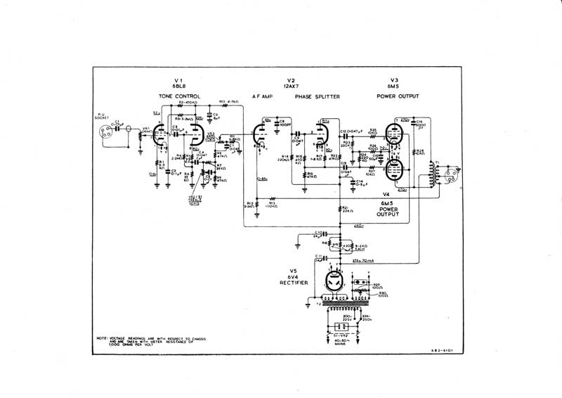
The schematic below is for a HMV G1 amp that I own and it is clear that the tone circuit is separate from the rest of the amp running from a 6BL8 valve and using 240 VoltsDC to run and 6.3VAC for the heater. Question is how much output in volts and amps is being put into the next stage. Maybe too much that might overload the 12B4? I suppose I'd need to measure those things? Sorry to be a nuisance about this but if this looks possible it would be interesting and a good thing.
Member
Joined 2009
Paid Member
I have a clone Marantz 7 line stage preamp that i assemble from a kit, some 20 years ago.
It's a good way to get started since there's a lot of information to help. The alternative is this thread, where nothing is going to get finished. Don't ask me how I know, or how many unfinished threads I started when I didn't know better 😀
Well being new at least gives me hope. So I hope to prove you wrong there. Just waiting for the bits to arrive. I have fully understood now about me not doing the tone control. It is verboten and I will cease and desist from any further reference to it. It's a case of fools rush in......... I'm hoping to learn and finish the initial 12B4 preamp because I read some good reviews and I'm hopeful it's going to sound great with my Aleph. I haven't gone for a clone that is of Asian origin because I already have this Monoprice hybrid with valve preamp and line out , which is what I am listening to. It sounds very nice but being foolish and ambitious I want more. I still feel I can achieve more transparency but I might be dreaming. If you are correct and it all comes to nought I will probably try a kit but I'd be more attracted to Aikido even though they didn't answer my pig ignorant questions. They probably ignore a thousand every week. It would be a difficult industry to make work. I looked at Dynaco but frankly I just can't justify spending that much. The main board isn't too bad but you really need the whole thing and all the small ancillary parts push it to about $800USD before freight so that ends up being about $1500Aud landed. That isn't going to happen. My other possible plan is to copy the whole HMV amp which I own to make a pair of monoblocks. But that's for another day. Meanwhile thanks for your discouragement. I need some to keep me focused.
Member
Joined 2009
Paid Member
Well being new at least gives me hope. So I hope to prove you wrong there. .....I'm hoping to learn and finish the initial 12B4 preamp because I read some good reviews and I'm hopeful it's going to sound great with my Aleph....
hmmm, my post wasn't very helpful was it. Well I was getting frustrated with the thread. You asked for something that would make it easy for you and contained tone controls and didn't need gain but instead you've ended up with a gain stage and no tone or balance controls - which all seems bassackwards to me.
Well, now that you are committed I'd be happy to offer my limited experience. It's very limited. But here goes...
Firstly, I believe the actual pre-amp is the easy (fun) part. It always seems to be a long journey to get to the final part where you wire that up. Rather there's a lot of effort needed to obtain all the parts, then cut all the holes in the chassis. It takes me way longer to do that part than the wiring in most cases. So my first piece of advice is in line with your thoughts back in post 33, to sit down with a decent sized virgin chassis and plan where all the parts are going to fit - power input, RCA, controls, transformers etc. Draw out a paper plan and check it. Then cut all the darn holes and check that all the parts fit. Don't forget somewhere to screw/bolt in a safety earth connection to the chassis. Drill holes large enough to fit rubber grommets where wires will pass though the chassis from top mounted transformers. Once it's all finished, then maybe paint it if you fancy.
Last edited:
Member
Joined 2009
Paid Member
In terms of the chassis layout, you'll want to have the power supply kept away from the pre-amp wiring to reduce magnetic coupling etc. For example, put the power supply on the left hand side of the chassis and the pre-amp circuitry on the right hand side of the chassis.
Build the power supply first, test it out with a dummy load.
One thing you might also try, just for learning, is to load the tubes with a resistor instead of the solid state current source. There's a few reasons for suggesting this experiment. It's simpler for starters (and more traditional if you like that kind of thing), it will provide a slightly better (lower) output impedance, a little less gain and it's distortion profile might be a bit more tube-like but you'll lose some headroom for very large signals. It costs you little to try and you may well prefer it. The 12B4A has an internal resistance around 1k ohm and a load resistor of at least 3x this would be a good place to start, i.e. 3k ohm. You may or may not just have enough B+ voltage to accommodate a 3k load at 20mA but a little less current through the tube (e.g. 15mA) will give you more headroom. It's always wise to have extra resistors of different values on-hand in your parts bin when you are doing bench-work like this. For example, to reduce the current through the tube, you'd want to increase the cathode resistor from 500R by 10%, 20% etc.
- Home
- Amplifiers
- Tubes / Valves
- A Noob Valve Preamp Build?