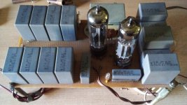
After emigration to Panama I quickly realized that analogue radio in Latin America was to stay for many years so I ransacked eBay listings to find these gems. Had my mechanical skills been worthwhile, they had been in use already. Occasionally eBay still has some on offer, like this one:
https://www.ebay.com/itm/114996416960?hash=item1ac65211c0:g:JfsAAOSwEsphRQDpBTW tube-based FM receivers easily could outperform commercial standard semiconductor designs. Back then my all tube FM RX applied 2nd conversion and a 3rd conversion allowed the use of counting detector. But (like everyone else) I missed the idea to use a 7360 or 6JH8 as VCO + phase detector for a 1 tube PLL demodulator... The front end could use the already audio-famous 6E5P in cascoded triode mode as that ~halves Req from 350 to ~175R
https://www.ebay.com/itm/114996416960?hash=item1ac65211c0:g:JfsAAOSwEsphRQDpBTW tube-based FM receivers easily could outperform commercial standard semiconductor designs. Back then my all tube FM RX applied 2nd conversion and a 3rd conversion allowed the use of counting detector. But (like everyone else) I missed the idea to use a 7360 or 6JH8 as VCO + phase detector for a 1 tube PLL demodulator... The front end could use the already audio-famous 6E5P in cascoded triode mode as that ~halves Req from 350 to ~175R
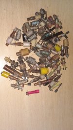
If the receiver prosperates well, the idea is to make a stereo decoder but based upon diodes of the 6JU8. I owned several of them. They are like a dual 6AL5 diodes in a single bottle saving space. I run one of them rectifiying 200VAC and it performs ok. Possibly the coils I use will be horizontal TV ones as I have saved a lot of them. Actually I don't know if there is a SCA service on air here.
Analog FM is widely extended here mainly small clandestine ststion that interfere mutually. I counted almost 7 in a 1km radii.
The stereo decoder I imaginated will use the old approach of doubling the 19KHz pilot and use it to the balanced detector previously amplified and filtered.
Analog FM is widely extended here mainly small clandestine ststion that interfere mutually. I counted almost 7 in a 1km radii.
The stereo decoder I imaginated will use the old approach of doubling the 19KHz pilot and use it to the balanced detector previously amplified and filtered.
Last edited:
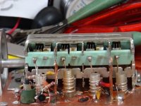
Small progress. The ECC189 RF cascode amplifier. Final tube will be ECC88 with higher gm, but as it is expensive, during test the former will be used. Base connections are the same.
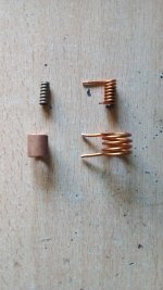
Below, at first intance, the coils, the screwed core for padder inductance, the copper core re-coppered and the main tuning inductor.
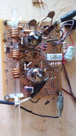
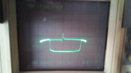
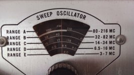
Next, the amplifier mounted in the protoboard, the sweeped waveform showing the carrier beating with the oscillator and the sweep generator dial showing the frequency. Consider that the dial doesn't coincide with actual frequency when measured the output with a digital frequency meter. Note also an undesired 50Hz signal that makes the sweep baseline non straight. I couldn't find where it enters in the signal path but momentarily it doesn't care too much.
Below, at first intance, the coils, the screwed core for padder inductance, the copper core re-coppered and the main tuning inductor.
Next, the amplifier mounted in the protoboard, the sweeped waveform showing the carrier beating with the oscillator and the sweep generator dial showing the frequency. Consider that the dial doesn't coincide with actual frequency when measured the output with a digital frequency meter. Note also an undesired 50Hz signal that makes the sweep baseline non straight. I couldn't find where it enters in the signal path but momentarily it doesn't care too much.
Attachments
Progress looks good. Filtering, amplifying the 19k pilot and producing the 38k switching signal works so well that it also was used in semiconductor decoders. It leaves the choice to using frequency or time multiplex (as possible with the Philips TDA1005A). With plenty of TV coils at your disposal, the first would be the better alternative as the level of annoying "birdies" (translating to "fuzzy" sound is much lower.
Here, the difference between "pirate" and "legal" radio is hard to tell as everyone can rent bandwidth plus coverage. But on the SDR the spectrum of most signals look bad, with 38k plus harmonics present and overmodulation, sometimes to the extent that the AFC of the station is exceeded.
Here, the difference between "pirate" and "legal" radio is hard to tell as everyone can rent bandwidth plus coverage. But on the SDR the spectrum of most signals look bad, with 38k plus harmonics present and overmodulation, sometimes to the extent that the AFC of the station is exceeded.
Update: I found a break connection between one anode of the EZ81 and the trafo causing too high ripple and oscillation of the ECL82 voltage regulator. Tomorrow let's see if the reference line in the sweep is straight as it must be.
Attachments
Adding the antenna-cascode's grid matching element. A resonator similar to the above but shielded inside a 25mm copper shield from plumbing tubing and axis rotated 90deg to reduce couplig as mutch as possible. Still unconnected but phisically mounted. Temporarily, the core command will be independent for mechanic complexity.
Attachments

Last edited:

I had such a tuning cap from an old DX-160, it has 4 VHF sections but 3 AM sections. As it's rather small I used it for an "all MOS" FM tuner: BF987 RF amp and single balanced mixer with 2X BF981, LO BF987. From switching on the LO is so stable that I omitted AFC. Measurement setup over a 24 hour period showed the LO stayed within 1k...
Attachments
Nice project! Did a similar tube tuner with four gang tuning cap. It has a cascode RF stage and a Revox-style IF filter and wideband IF limiter. Performance was a bit underwhelming and I aborted the project.
A pity that performance was below expectation, the project certainly looks nice. Osvado's project reminded me to finish my project, as it already reached the stage of PLL + counting detector. The other reminder was to finally work out the sensitivity issue in a way that simulation sorts it out for any device supported, verifiable by simple but crude measurement. For the (tuned) mosfet input, a 75 ohm source input results in ~0.13 uV noise (had been measured before sorting it out with simulation) but a broadband EC86 (Ayumi model applied in sim) circuit easily should get ~0.2 uV (applicable as antenna preamp), so your project might be improved.
The EC86 (aka PC86 with different Vf) is intended as self-oscillating mixer for UHF. I did notice that noise performance as MC phono amplifier was superior to its UHF input sibling PC88 so this may hold true for FM as well. I take it you used in grounded grid, being wideband and all? Otherwise the PC900 would be a better candidate but it would need neutralization because of Cag feedback. PCC88 and PCC189 are intended for cascode operation. The UKW project uses an ECC2000.
You could buy an old Blaupunkt car radio. Most of those that equiped german cars up until 2000 had a permeability mechanical tuning system with 4 cores.I might still have one in my home.I think i saw a Philips car radio also with that tyning system.In car radios rhey are also very compact.As far as i remember blaupunkt car radios had very good sensitivity and were highly appreciated back in the predigital era.
The first German (European?) UHF units in TV's had two PC86's, the 1st one as grid base input amplifier, the 2nd one as self oscilating mixer, as you said. A few years later the PC88 was invented to replace the 1st PC86.The EC86 (aka PC86 with different Vf) is intended as self-oscillating mixer for UHF.
This is true. Due to the high FM station densitiy here in Germany, following the Copenhagen conference setback, German FM tuners and radios needed to be selective as well as sensitive.As far as i remember blaupunkt car radios had very good sensitivity and were highly appreciated back in the predigital era.
Best regards!
Thanks all folks for the inputs and suggestions. The idea of an all-MOSFET receiver is also interesting. I had an old 11mts President McKinley modified to the ham 28MHz band via a 27C64 UVEPROM to tune from 28005 to 28995 in 99 channels 10KHz gaps, modifying the binary from the rotary switch to the PLL, and I replace almost all stages from bipolar to JFET or MOSFET stages with improved sensitivity and lower noise. Output stage was modified to a pushpull IRF110 with about 10W from 12V ps. Actualy thanks to the led lighting here HF bands are unusable. One of them causes interference in the 2M band, 147470 KHz.
A famous FM input circuit with tubes was a bridge, where the influence of Cag and Cac cancelled each other. Back then no attention was given to the issue that it's a case of grid-cathode negative feedback that could be optimized for minimum noise (works very well with semiconductors too, applied that in an active wideband loop antenna, to reduce RFI). It's unlikely that Cag and Cac influence canceling coincides with minimum noise but for a cascode one can optimize noise without instability issues. For a 75R source impedance, according to simulation, for the EC86 one can expect -190dBV/(sqr(Hz)) which is rather low.
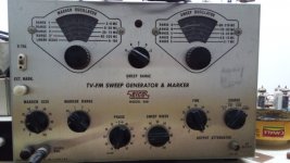
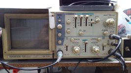
My instrumentation is very limited, to a 40MHz 'scope and the old resaured EICO 368 sweep generator. No way to measure sensitivities and noise. In mu case, I'll try to do as best thing as I can, but surely far away from optimal results and performance. I am satisfied if I can listen some few good programme stations, my principal source of entertaining is AM radio, mostly Rivadavia at 630KHz and Mitre at 790KHz. And some MP3's at my vintage AMD486's.
Attachments
My RF generator is a Marconi 2022A, goes down to 0.1uV output. For audio HP3585A, HF & VHF Advantest R3361A. However living in a very rural area means that signal strength is very low (exception, 2 commercial FM stations at 20 Km distance). Much RFI from digitally controlled power plants (hydro and solar) and none of my conventional radios and SDRs can eliminate it. The (otherwise perfect wideband) active loop would need frequent 3D adjustment to null it. So trying the best in this situation is to use 2 phased active dipoles (under construction) as here too, national AM is favorite and with "good enough for background music" audio quality (10 KHz audio, R. Cristal, 740 KHz, CHT 960 KHz, Festival 1540, R. Mensabe, 1410 KHz).
Where are you from, sir? Where are you living?.
Ok. Seems that digital noise is elsewhere contaminating the ether.
Ok. Seems that digital noise is elsewhere contaminating the ether.
I'm living in the West of Panama, near the border with Costa Rica. No industry, sparsely populated. A few years ago I thoroughly documented my case (still on Facebook) including even the effect of the RFI on milk production and ASEP had enough evidence to force the power company to insert low pass filters. Hurricane damage (via emergency laws) allowed elimination of those filters and I would have to open up a new case. Modern LED lighting is surprisingly quiet, so the most likely culprits in Argentina are power companies too. The (audio) signature of that interference can't be missed. The pic says more than the proverbial 1,000 words.
Attachments

- Home
- Source & Line
- Analogue Source
- A new FM tuner with Compactron Tubes