
Great effort. Nice amp indeed. The multi tone low freq behaviour - is that due to the 60Hz or something else?Assembling an floor test setup.
Please do use a bit larger pictures (both photos and screenshots) if possible - don't be afraid of say 1024 pixels width.
Thanks!
//
You mean 60 Hz?the 6hz has a very fat column
Try increasing fft window size.
Last edited:
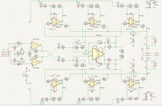
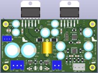
After successfully building the 6x LM3886 parallel-bridged amplifier, I looked back at the original single LM3886 and 2x LM3886 error-correction/composite amplifiers and felt that it's still necessary to take things a step further. At the same time. The goal is to improve and perfect the single LM3886 and 2x LM3886 error-correction and composite amplifiers, and to design a universal PCB that is compatible with both amplifier versions — bringing this round of exploration to a satisfying conclusion.
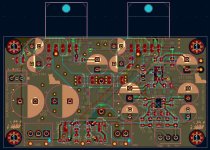
Through the construction of the 6x LM3886 amplifier, I gained a better grasp of circuit structure, more confidence in component parameters, and was able to further optimize the PCB layout.
At the same time, during the building and testing of the 6x LM3886, I experienced the advantages of a fully balanced circuit. For the first time, I saw in the test that the 60Hz AC background noise peak was flattened in the FFT (with a switching power supply) or significantly reduced (with a conventional linear power supply). Therefore, the first major change in this circuit is the adoption of balanced signal input; the second improvement is the removal of redundant small capacitors that were shown in the first and second versions to have little effect on stability, simplifying the circuit; the third improvement is retaining the jumper option to select between error-correction/composite amplifier modes, enhancing flexibility and playability; the fourth improvement is using a combination of surface-mount and through-hole components.
Attachments
I like it, too.
It is very easy to swap LM3886 if ever needed. The top pins can pop up by themslf after remelting the joint. The bottom pins can be take off one by one very easily.
It is very easy to swap LM3886 if ever needed. The top pins can pop up by themslf after remelting the joint. The bottom pins can be take off one by one very easily.
And much easier to lay traces when both sides are readily available , free from holes. Did it many years ago, but by far not as sophisticated as you. 👍
Present Tube:
Now I finally restarted this hobby, armed with fantastic articles from here and elsewhere and new simulation and measurement tools life is so much easier today.
Quickly realized that this driver with extremely low Q has nothing to do with sealed box, and modified whole thing again.
I started with 90mm sewage pipe for bass reflex, result was horrible whoops and puffs. Ended with 130mm sewage tube and it is much better. The reflex pipe I managed to flare with heat gun and piece of steel pipe. I carpeted inside and filled with fiberglass wool.
On the pictures you will see whole...
Last edited:
Try adding one space before the link. Or insert the link without line break: https://www.diyaudio.com/community/posts/7602196/always embeds
I did a simple guide how to solder LM3886 after all SMD are soldered.- Cut all NC (Not Connected) pins – These are pins 2, 6, and 11.
- Double- and triple-check before cutting – Mistakes are irreversible once pins are cut.
- Begin soldering from the bottom of the PCB – Align the component pins with the pads as shown in the reference image, and solder only one pin initially.
- Re-align if needed – Reheat the soldered pin to adjust alignment, ensuring the pin sits flat on the pad.
- Solder the remaining two pins once alignment is confirmed.
- Mount the PCB onto the heatsink using 4.5–5 mm standoffs. Firmly secure the LM3886 to the heatsink, ensuring good thermal contact with even surface contact.
- Insert a 0.5 mm diameter solid copper wire between the edge of the PCB and the top row of LM3886 pins.
- Bend all top pins upward by about 30 degrees, starting 2 mm from the pin tips, using needle-nose pliers.
- Solder each top pin – Push the pin toward its corresponding pad, solder it firmly, and hold it in place until the solder joint is fully solidified. Ensure the joint is strong and adequately sized before releasing.
- Pull the wire out after all top pins are soldered.
- Take the PCB from the heatsink and solder all through-hole components.
The standoffs cannot be too high and too low.
This kind of LM3886 mounting can save a lot of space inside the chassis and don't need an assistant bracket.
This kind of LM3886 mounting can save a lot of space inside the chassis and don't need an assistant bracket.
Great , practical and useful post wwwttt! If you did not write it, I would at some stage. Ill remember it and link when needed.
One extra tip, if 2 single sided boards are used glued together (instead of double sided PCB), their thickness is just bit less than LM3886 distance between odd and even pins, not even bending is needed.
One extra tip, if 2 single sided boards are used glued together (instead of double sided PCB), their thickness is just bit less than LM3886 distance between odd and even pins, not even bending is needed.
By any criteria better than soldering through holeMechanical reliability ?
Hi, in this thread I linked 6 pack of LM3886 on one double sided board, pins bended, no mounting screws needed. Post #109 above.@Drbulj never thought of putting 2 boards together.
This is very simple execution with double board glued, for motor drive amp, but doesn't matter, it is same TO220 multi-watt housing.
https://www.diyaudio.com/community/...eded-with-motor-and-drive.412984/post-7918333
Sure you can glue 2 double sided boards and even have some circuits in the middle.... real diy
- Home
- Amplifiers
- Chip Amps
- A New EC-Composite LM3886 Amp