I decided to start another tube tracer thread to discuss a new project.
What I want to do is build a fully programmable tube tracer/tester using the Arduino microcontroller to control the measurement steps.
The design is very simple, consisting of the Arduino with an external 10 bit D/A converter, driving three programmable pass regulators (Vg1, Vg2, Vplate). The Arduino has enough onboard 10 bit A/D channels to measure all the electrode currents.
At each measurement point all three regulators would be pulsed on only long enough to settle and measure, then returned to a baseline state. The baseline state could produce some known idle dissipation if needed. The dissipation during measurement can be limited by limiting the duty cycle.
Producing a set of plate curves would involve running enough measurement points in any order such as to connect the dots and draw curves.
The electrode power supplies would each be isolated with shunt current measurement on the ground side. Safe, easy, cheap. All one needs is 3 separate secondary windings e.g. Antek toroids, etc. and relatively small ones at that (50-100VA should be sufficient due to the short duration of the measurement pulses).
The status of this project is I have the necessary parts and Arduino testbed, I have obtained an A/D converter (AD7808), and am currently prototyping the programmable pass regulator design. I plan to build one PCB for the Arduino D/A shield, and another PCB for the programmable pass regulator (3 regulators needed for each tracer). The regulator board will carry the rectifier, filter/storage caps, and current sensing with protection circuits.
The other part is some manual range selection so one can test power tubes and small signal tubes using the 10 bit A/D, e.g. electrode current ranges of 1mA, 10mA, 100mA, 1A. Grid voltage range 20V, 200V. Manual g3 bias setting would probably be sufficient but another regulator could be added.
I'm also intrigued at the idea of physical tube modeling, where Spice would provide inputs to the tracer, the tracer would make measurements, and provide the results back to Spice to use in the circuit model.
The arduino provides USB, serial, and IP interfaces, but it seems like USB would be a good method.
This project would be fully open hardware and software, allowing anyone to build it for any purpose including commercial products.
Cheers,
Michael
Last edited:
For a start, I recommend a design definition along with block diagrams would be a good first step. From this determine the functions and number of I/O necessary and then determining which Arduino would be optimal for the project. The difficult part is determining the amount of internal resources which will be necessary (Flash, RAM, etc).
In addition, bit banging several serial DACs may consume a lot of time from my limited experience with the 89C51 driving three DACs and two ADC channels at a time. I ended up going to parallel DACs. The Arduino may be faster, best to benchmark it before getting too far into the design.
This thread came about from this one:
http://www.diyaudio.com/forums/tubes-valves/173255-diy-curve-tracer-8.html
Last edited:
For a start, I recommend a design definition along with block diagrams would be a good first step. From this determine the functions and number of I/O necessary and then determining which Arduino would be optimal for the project. The difficult part is determining the amount of internal resources which will be necessary (Flash, RAM, etc).
In addition, bit banging several serial DACs may consume a lot of time from my limited experience with the 89C51 driving three DACs and two ADC channels at a time. I ended up going to parallel DACs. The Arduino may be faster, best to benchmark it before getting too far into the design.
This thread came about from this one:
http://www.diyaudio.com/forums/tubes-valves/173255-diy-curve-tracer-8.html
Good points. I do have a block diagram and know that the Uno has enough I/O. Today I'm documenting some of this in electronic form so I can post it.
Internal resources depend on how complex the internal logic needs to be, but my experience so far is encouraging for the Uno being able to run at least plate curves autonomously from start-stop-step parameters while pushing the data out the USB. Current idea is to make a measurement, then spit out the data before making the next measurement, which provides a cooling off period between measurements. A storage card could be added to store data sets etc. but I see most of the heavy lifting being done by an attached PC running python scripts. I wouldn't want to program heavy analysis using the pidgin C of the arduino SDK. It's mainly for sequencing and interfacing.
I looked at both serial and parallel and for Arduino it's really about a wash as there's no instruction to load a word to a port but good support shifting data bits out a serial line...
The AD7808 D/A has a global load so I can preload the data registers and then pulse the load signal to change all outputs together. On the measurement side, I don't think a few A/D conversion cycles will be a problem but I will let you know the timing when I have made a measurement later on. I still need to hook up the 7808 to the Arduino.
I should point out that one big goal is to keep it simple. At first all I care about is generating plate curves by importing CSV data into MS Excel. Manual range switching. Minimal programming. It's super easy just to download different arduino code sets for different tester/tracer functions. This can get way more sophisticated as time goes on and if others get interested in making improvements, commercializing, etc.
Last edited:
Sounds like an excellent idea. Keep in mind some isolation between tester and PC.
The PC side (for physical tube modeling, can do some interpolation between measurements to improve Spice speed, just needs some predictive (derivatives) modeling to locate the next test samples needed)
Seeing as you have programmable voltages planned available, another very useful function can be performed besides tube curve tracing. You can measure circuit gain versus some parameter like DC input bias or screen voltage or plate voltage. Just need a 1 KHz say oscillator for a test signal and a 1KHz selective detector (converts amplitude to a DC level for the A/D) for measuring the output level. Then plot variation of gain (from the mean) versus the swept parameter.
My vote is for an IP/ethernet interface rather than a USB interface. The handling of TCP/IP and UDP is much more platform independent than USB. Makes writing the host software in something like Python pretty easy. That's my vote anyway.
~Tom
~Tom
My vote is for an IP/ethernet interface rather than a USB interface. The handling of TCP/IP and UDP is much more platform independent than USB. Makes writing the host software in something like Python pretty easy. That's my vote anyway.
~Tom
If you are using an Arduino then it already works across Windows, Mac and Linux. The Arduino looks like a USB serial device the PC.
But I suspect many people will want to use the curve tracer stand-alone without a cable going to a PC. It is very easy to add an SD memory card to an Arduino. Easy to add Ethernet too. and Easy to do BOTH because the Ethernet shield just happens to also have an SD card on it. So if you add Ethernet you get SD.
My plan, and now it looks like we have at least a few people working in the same general idea is to have four programmable voltages out. These can use the built-in 8-bit DACs But I will also measure the voltage and not depend on a DAC controlled pwer supply to be accurate, that would cost to much. Easier to close the loop in software. Also for each power supply I will measure current using a 1 ohm resistor.
With this setup I can servo, in software a constant current or a constant voltage on one pin while the other pin is swept.
If serial DACs/ADC is used I'd look a the "mega" rather than the "Uno" version of Arduino because the Mega has hardware UARTs and you avoid "bit banging".
A big part of the design is the opto-couplers. I CERTAINLY want optos between the high voltage and the Arduino. It takes some effort to pass a linear analog signal through an opto. However serial data like I2C can work easy with an opto. I have yet to work out a parts count and cost for each method.
The other part of design is the user interface. I'm thinking of using a 2x16 character LCD and a rotary encoder, the kind with a push button on the shaft.
One more idea: Build a "library". ("Library" as a rather exact meaning when using an Arduino.) To abstract away difference between Serial and parallel DACS and so on. Just have exposed functions like "set_plate_voltage()" or "get_cathode_current()". Then if people modify their hardware the top level control routines don't change.
The issue with USB serial ports, is that many times it shows up as a different port every time. So sometimes it may be COM1 at other times it's COM4. That's pretty annoying. An IP address is always the same and implementing UDP discovery isn't a huge deal. But that's my preference.
It's not that hard to get linear signals through opto couplers. Use two identical opto couplers (a dual type is preferred). Hook the LEDs in series and drive the current through them with an op-amp. Use one of the photo transistors as the feedback to the op-amp, use the other to drive the isolated side. I can draw a schematic for you if you're not familiar with the circuit.
~Tom
I have tossed this idea around in the back of my head for a couple of years now. Life's little roadblocks have kept my soldering iron cold since last October, but that is slowly improving. I had similar hardware ideas but you need to think about what to do with the data once you have it. Full curve plotting and tube matching is only a bit of code away. I considered the Arduino, and it may still ba a valid choice, but I thought what if there was an Arduino with BALLS. 32 bit's worth......
Digilent Inc. - Digital Design Engineer's Source
Not telling anyone what to do but, I already have two of them and an ethernet shield.
Digilent Inc. - Digital Design Engineer's Source
Not telling anyone what to do but, I already have two of them and an ethernet shield.
A big part of the design is the opto-couplers. I CERTAINLY want optos between the high voltage and the Arduino. It takes some effort to pass a linear analog signal through an opto. However serial data like I2C can work easy with an opto. I have yet to work out a parts count and cost for each method.
We use the IL715 and IL711 chips at work for isolation. Pretty interesting because they are coupled magnetically. These days digital is the way to go.
http://www.nve.com/Downloads/il71x.pdf
The other part of design is the user interface. I'm thinking of using a 2x16 character LCD and a rotary encoder, the kind with a push button on the shaft.
One more idea: Build a "library". ("Library" as a rather exact meaning when using an Arduino.) To abstract away difference between Serial and parallel DACS and so on. Just have exposed functions like "set_plate_voltage()" or "get_cathode_current()". Then if people modify their hardware the top level control routines don't change.
I think an application running on a PC is going to be better than doing a local control. Scrolling through menus on a small LCD is not fun. TCP/IP is nice but adds some complexity.
Thanks for all the comments.
I've thought a lot of this through and concluded that using return side current measurement makes isolation not an issue IMO.
The beauty of this approach is that the horsepower of the engine is scalable from Uno level up to the Maple and other 32 bit variants. As I mentioned, I think most of the heavy lifting in SW belongs on a PC, but it could easily be done the other way.
Also I don't think Arduino has a built in D/A at all; there are some PWM channels. I plan to add a $20 8 channel 10 bit D/A that allows synchronous control of all outputs simultaneously. It hooks up to the Arduino using 3 signals.
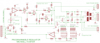
I think that the regulator is also not so difficult to implement with a control voltage in and current measurement out. Attached is a basic design I'm using as a starting point. It can be configured for either bipolar operation for control grid, or unipolar operation up to 600V for plate or g2. I do think the range selection is needed to accommodate different power tubes and draw smooth curves with 10 bit A/D resolution. I need to measure plate current from 1mA to almost 1A to cover the full range of tubes.
I've thought a lot of this through and concluded that using return side current measurement makes isolation not an issue IMO.
The beauty of this approach is that the horsepower of the engine is scalable from Uno level up to the Maple and other 32 bit variants. As I mentioned, I think most of the heavy lifting in SW belongs on a PC, but it could easily be done the other way.
Also I don't think Arduino has a built in D/A at all; there are some PWM channels. I plan to add a $20 8 channel 10 bit D/A that allows synchronous control of all outputs simultaneously. It hooks up to the Arduino using 3 signals.
I think that the regulator is also not so difficult to implement with a control voltage in and current measurement out. Attached is a basic design I'm using as a starting point. It can be configured for either bipolar operation for control grid, or unipolar operation up to 600V for plate or g2. I do think the range selection is needed to accommodate different power tubes and draw smooth curves with 10 bit A/D resolution. I need to measure plate current from 1mA to almost 1A to cover the full range of tubes.
Attachments
It's not that hard to get linear signals through opto couplers. Use two identical opto couplers (a dual type is preferred). Hook the LEDs in series and drive the current through them with an op-amp. Use one of the photo transistors as the feedback to the op-amp, use the other to drive the isolated side. I can draw a schematic for you if you're not familiar with the circuit.
~Tom
No, not a "dual type opto" because think of the chip as having a "hot" side" and a "safe side". Using a dual chip means you have a wire or a PCB trace that crosses the opto's center line. I'd prefer a slot milled in the PCB right down the center of the opto chip. Or at least a ground trace with no mask over it. Think of dirt and crud as a conduction path. They make an IL300 opto that has two receivers and one transmitter, They are matched receivers. So, yes it can be done. But then you also do the design using serial. Then you compare the two BOMs, look at cost, square inches and performance.
I still think it could go either way. But if a library abstracted the hardware then it hardly matters. You call "get_plate_voltage()" and don't worry to much the details of how it works after it's built.
...
I think that the regulator is also not so difficult to implement with a control voltage in and current measurement out. Attached is a basic design I'm using as a starting point. It can be configured for either bipolar operation for control grid, or unipolar operation up to 600V for plate or g2. I do think the range selection is needed to accommodate different power tubes and draw smooth curves with 10 bit A/D resolution. I need to measure plate current from 1mA to almost 1A to cover the full range of tubes.
One thing I'd add is "voltage measurement out". Yes you know the control voltage you send using your serial DAC but knowing the volts dropped would not be exact. It depends in the setting of the pots that control the feedback to the op amp. It would be easy to place a voltage diver (10:1) across the output and send it to an ADC.
I agree about a range selection. A relay and a multi-tapped power transformer would be ideal. My plan however is to use an existing bench B+ power supply and with the above "voltage measurement out" I would measure the incoming voltage from the bench supply.
If you publish this for others to build, everyone will use a different power transformer and you'd like the software to auto-scale.
Thanks for all the comments.
I've thought a lot of this through and concluded that using return side current measurement makes isolation not an issue IMO. ...
Yes it will be 100% safe until a component fails or a wire breaks some other thing happens that you did not plan for.
Remember the Ford Pinto. It was perfectly safe as long as you never had an accident.
The purpose of the opto is to be fail safe in the advent of an accident, dropping a screw into a chassis and not noticing should not cause a fatal injury to the user. same if a mosfet overheats and melts pvc insulation off a wire.
If optos are to expensive then at least place a zenier diode on every conductor leaving the metal high voltage enclosure so it is clamped to about 7V. I'd do both
Also and this is a big deal. It's a tube tester right? So before long someone will try to test a bad tube that has shorted elements. You have to make the power supply "short safe".
The short might be to ground or between elements. Also I assume there are some switches or a plug board so different pin-out tubes can be tested and maybe there are many sockets but in any case there is chance of a user error that could do ANYTHING like place 500 volts on the heater you just can't know.
What if you have a software bug that sends 500 volts from a 1 amp supply to a small preamp tube and it melts the physical structure inside the envelope? Any random combination of pins might now be shorted together.
No you can't test for shots in advance of applying power, the power might cause the short.
Bottom line is that you have to plan for things you'd can't foresee
Last edited:
Great comments, ChrisA. I'm not building a Pinto😱
I am planning for current limiting the power supply such that a short will not blow anything up. Pulse measurement allows me to limit the continuous current to the tens of mA range in the event the SW tries to continuously apply voltage to an electrode. Switching the range could also switch the current limit.
With proper current limiting and zener clamps there should be no problem with shorted tubes causing damage or safety issues. It should be pretty hard to even blow up a tube.
Readback of the electrode voltage would be useful to diagnose shorts or miswires. The additional A/D channels are available and it would only need another opamp for scaling the measurement.
I'm planning a single voltage range scaled by the feedback resistors for plate and g2, and 2 voltage ranges for the g1. Note that the g1 voltage scaling isn't shown on the regulator circuit yet. Someone building this would be able to scale things to their own needs.
Heaters will be powered by dedicated transformers which allows for isolation and a safe return path in the event of shorts or miswires to heater pins. The cathode will be grounded through a small value resistor for current measurement.
Additionally, with this design a low voltage can be applied to test for shorts before blasting the tube with 600V.
If you have any more safety comments please refer them to the specific design being proposed.
Thanks!
Michael
Last edited:
Isolators?
Can someone show me a rough sketch of how one of these isolator components being proposed would actually be used (for example) in a plate current measurement circuit?
It occurs to me that using the pulse measurement technique would enable a simple transformer to be used as long as the measurement interval is short enough to keep the core from saturating (!)
Cheers,
Michael
Please pardon me for butting in, here, but...
Some of you guys are getting down into the weeds way too fast.
Planning comes first and then, much later, implementation details are considered, only after everything has been planned: required capabilities are selected, then required functions are derived from capabilities, then specs are derived from functional requirements, then a top-level functional modules' architecture is selected after analysis of alternatives, then the top level functions are decomposed to smaller or lower-level functional modules, which all should be traceable back to capability requirements. Then the same entire process is applied recursively to each of the lower-level modules, until finally there is a set of lowest-level modules, that are implementable. THEN you can discuss how to implement them as circuits (or whatever they need to consist of). (And then eventually you start going back up the other way, from components to circuits to modules and finally to a complete system, verifying specs and functionality of lower-level modules as you go, before combining them into larger modules or eventually into a complete system.)
You will consider alternatives based on some of the details of how they might be implemented as circuits, before that, of course, but even at that point you're still not ready to go as deep as where you're trying to already jump to.
Doing things properly, in sequence, and spending more time planning at the beginning, can definitely save both time and money, and should get the best end result.
Maybe the first thing for everyone to come to terms with is: Whose thread is this and what is its purpose?
Michael Koster is the thread starter. So he can decide that, if he wishes. And he does seem to already have some things planned and some implementation details more-or-less decided.
So if there are others who would like to start back at the initial planning stage, it wouldn't hurt to start a different thread. It would probably be beneficial to both.
Last edited:
Can someone show me a rough sketch of how one of these isolator components being proposed would actually be used (for example) in a plate current measurement circuit?
It occurs to me that using the pulse measurement technique would enable a simple transformer to be used as long as the measurement interval is short enough to keep the core from saturating (!)
Cheers,
Michael
The Application Note from Vishay appears to be updated from the version which I have -- see figures 8 and 10.
http://www.vishay.com/docs/83708/appn50.pdf
The material is equally applicable to the HCNR200 -- there's a spice model for this part on the Avago datasheet (Avago Technologies Semiconductors Analog, Mixed-signal and Optoelectronic Components and Subsystems) -- used to be Hewlett Packard's semi biz.
Wouldn't it be a lot simpler to just put one opto set in the serial USB link?
I guess there was (is?) some backward compatibility issue with analog impedance on the USB line, but can't that be dispensed with now?
I guess there was (is?) some backward compatibility issue with analog impedance on the USB line, but can't that be dispensed with now?
- Status
- Not open for further replies.
- Home
- Design & Build
- Equipment & Tools
- A micro-programmable tube tracer/tester