I just ordered 10 sets (left and right channels) of PCBs from JLCPCB. Total cost was just over US $27 including DHL shipping. Cost of boards was $10 so hopefully no customs charges. These will be available at cost plus postage.
I plan to attend Burning Amp this year so I will bring what's left to hand out.
Edit: I almost forgot. I have 4 sets of PCBs from my first order which are available immediately.
I plan to attend Burning Amp this year so I will bring what's left to hand out.
Edit: I almost forgot. I have 4 sets of PCBs from my first order which are available immediately.
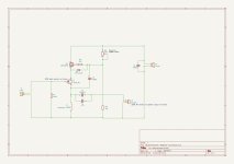
I have updated the KiCad schematic to include component values.
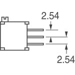
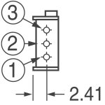
Also shown, are some dimensions for the 20k ohm trimmer potentiometer, R4. (Bourns 3296X-1-203LF)
C1 is an electrolytic capacitor with 22mm diameter and 10mm lead spacing. (Nichicon LGU1E103MELZ)
C2 and C3 are electrolytic capacitors with 10mm diameter and 5mm lead spacing. (Kemet ESH108M025AH4AA)
C4 is a film capacitor, 26mm x 12mm, with 22.5 lead spacing (Panasonic ECW-FE2W475K)
In brackets are the components which I used. I picked them for their value and expected life. I do not know what their audio attributes are, but they do the job.
Attachments
Thanks to Bill to share a pair of his PCBs and I started building the amp keeping in mind the low wattage outputs that I was also looking at considering my Forte III. Here is the build so far
I partnered with @Vunce and we exchanged his pair of soldered JFETs with mine as I was not comfortable with the aluminium PCB soldering 🙂 Thanks Vunce

Rather than getting another toroidal and making a single rail supply PSU I reused my ACA Mini meanwell laptop adapter rated 24vdc 2A to test one of the channels. Also used MJ VFET psu filter and the psu output is stable 22.67vdc. Everything else is as per Bill's schematic except that I had a spare set of 193T inductors which are not much different to the suggested 159ZC with similar 0.7 resistance. Now I am checking the voltage drop across the inductor and I get a lower to 1.112v and based on ohms law calculation taking resistance of 0.7R I am getting 1.59A bias current. But the offset started at 990mV then realized that I need to add the 220R/3W resistor across the speaker outputs so adding that dropped the offset to near 0. Shorting the inputs I was able to use the 20k trimmer to bring down the bias across the inductor to 1.0512 which gives the 1.5A.

Proceeded with the amp testing on my Wharfedale D210 85db monitor speakers using my MacBook as the source/volume control I see that the music is sounding at a very low volume even though I have set MacBook to 100% volume. Not sure if its the headphone output as I did this same setup with my earlier VFET amp having similar 10wpc rated and volume used to be pretty loud. Also I observed that the mosfet IRFP250 gets nice warm/hot within mins but the JFET aluminium pcb is not even warm to the touch at least when I touched the mounted screws.
Any ideas what could be the issue with low volume on the amp output.
Thanks
I partnered with @Vunce and we exchanged his pair of soldered JFETs with mine as I was not comfortable with the aluminium PCB soldering 🙂 Thanks Vunce
Rather than getting another toroidal and making a single rail supply PSU I reused my ACA Mini meanwell laptop adapter rated 24vdc 2A to test one of the channels. Also used MJ VFET psu filter and the psu output is stable 22.67vdc. Everything else is as per Bill's schematic except that I had a spare set of 193T inductors which are not much different to the suggested 159ZC with similar 0.7 resistance. Now I am checking the voltage drop across the inductor and I get a lower to 1.112v and based on ohms law calculation taking resistance of 0.7R I am getting 1.59A bias current. But the offset started at 990mV then realized that I need to add the 220R/3W resistor across the speaker outputs so adding that dropped the offset to near 0. Shorting the inputs I was able to use the 20k trimmer to bring down the bias across the inductor to 1.0512 which gives the 1.5A.
Proceeded with the amp testing on my Wharfedale D210 85db monitor speakers using my MacBook as the source/volume control I see that the music is sounding at a very low volume even though I have set MacBook to 100% volume. Not sure if its the headphone output as I did this same setup with my earlier VFET amp having similar 10wpc rated and volume used to be pretty loud. Also I observed that the mosfet IRFP250 gets nice warm/hot within mins but the JFET aluminium pcb is not even warm to the touch at least when I touched the mounted screws.
Any ideas what could be the issue with low volume on the amp output.
Thanks
Nice work so far Manniraj.
Being a follower type amplifier, it probably needs a preamp with cojones to get higher output.
Being a follower type amplifier, it probably needs a preamp with cojones to get higher output.
I just measured the voltage drop across the inductor per Bill initial setup suggestion. Let me measure other voltages as per the above spice file and check. But as Vunce said I guess it needs a good preamp with good swing to make it come alive. For now I have a HPA clone, SCG and iron preamp to test it out 👍 What do you suggest @Vunce to use the preamp and Iron preamp right now I am using the 6db but can change to 12db gain if required or HPA or SCG modified per latest updates from Rahul?If you bypass the input signal do you get the same results? A hot mosfet with a colder LD1014 ?
The voltages around your JFET, are they similar to the simulation (pics) ?
View attachment 1210786
Last edited:
Good work, Ramesh!
Yes, the JFET will have much lower power dissipation than the MOSFET. The cascode at work.
Another good preamp with good voltage swing is the Front End 2022. Inexpensive, too. Ben Mah raves about it.
Yes, the JFET will have much lower power dissipation than the MOSFET. The cascode at work.
Another good preamp with good voltage swing is the Front End 2022. Inexpensive, too. Ben Mah raves about it.
Thanks guys I finished the FE2022 and now the amp sings beautifully with my test monitor speakers 👍

FE2022 I am using the 10k pot as that’s the spare pot I had need a better one I suppose but not sure what value is ideal for this combo.
FE2022 I am using the 10k pot as that’s the spare pot I had need a better one I suppose but not sure what value is ideal for this combo.
Oh yes much better than without any preamp or direct MacBook as the source. But I need to get a good chassis to put this amp and put it to my main setup as I do not want to risk my Klipsch with all hanging wire all around 🙂 I have also got a beefier smps with 24v 5A and using MJ's VFET filter more than enough and do not require the toroidal+psu combo.
Thanks
Thanks
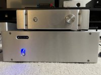
Finished the amp with the RTR speaker protection modules. Connected the amp along with the FE2022 to my klipsch and it just nails all my amps 😊

- Home
- Amplifiers
- Pass Labs
- A Low Power Cascoded LD1014 Choke Loaded Source Follower


