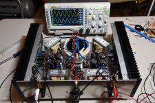
I finished putting the amp together this evening and double checked all the wiring. I was going to go to bed and wait until tomorrow to power it up. But, in the end, I couldn't resist the temptation to try it out. I know with all my testing at the various stages that everything should be good, so I went for it.
I was rewarded with both channels producing the test signal and nothing was smoking.
Now, I can go to bed.
I was rewarded with both channels producing the test signal and nothing was smoking.
Now, I can go to bed.
Attachments

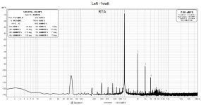
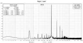
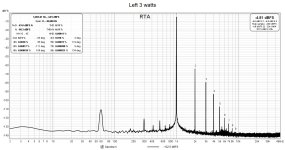
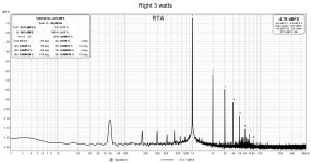
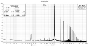
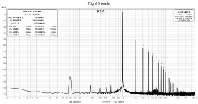
I made some measurements on the amp today.
The power supply settled down to 17.5V under load.
I had arbitrarily set the cascode MOSFET gate voltage using the voltage divider trim pot to 10k ohms which in conjunction with the fixed 10k ohm resistor results in 17.5V/2 = 8.8V to the gate of the cascode MOSFET. This produced 3.85V at the JFET drain and 1.24V at the source. This results in Vds = 3.85V - 1.24V = 2.61V. The current is 1.24V / 0.7 ohms (the resistance of the choke) = 1.77A. The total power dissipated is 17.5V x 1.77A = 31 W/channel.
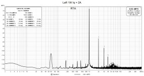
I used REW to make some distortion measures at 1W, 3W, and 9W into an 8 ohm load. These results can be improved on by changing the cascode operating parameters. Increasing the MOSFET gate voltage will increase the JFET's Vds and Iq for likely lower distortion and more power output (and of course, more heat produced). This was the case for the test prototype.
The power supply settled down to 17.5V under load.
I had arbitrarily set the cascode MOSFET gate voltage using the voltage divider trim pot to 10k ohms which in conjunction with the fixed 10k ohm resistor results in 17.5V/2 = 8.8V to the gate of the cascode MOSFET. This produced 3.85V at the JFET drain and 1.24V at the source. This results in Vds = 3.85V - 1.24V = 2.61V. The current is 1.24V / 0.7 ohms (the resistance of the choke) = 1.77A. The total power dissipated is 17.5V x 1.77A = 31 W/channel.
I used REW to make some distortion measures at 1W, 3W, and 9W into an 8 ohm load. These results can be improved on by changing the cascode operating parameters. Increasing the MOSFET gate voltage will increase the JFET's Vds and Iq for likely lower distortion and more power output (and of course, more heat produced). This was the case for the test prototype.
Attachments
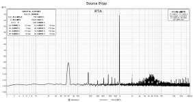
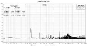
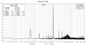
I used an old Acurus L10 preamp to boost the output of my Victor 1 kHz oscillator in order to drive the amp for tests. For completeness, here are the results of the distortion measurements for the source signal.
Attachments
I made some adjustments to the amp this morning. I'm trying to finalize the setup.
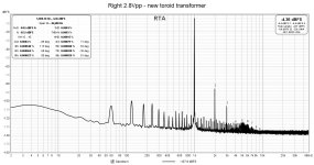
I rotated the power transformer to try to minimize noise at the output and was able to drop the noise levels a small amount. Sound wise, probably not audible.
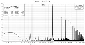
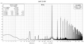
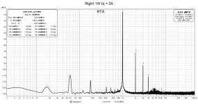
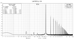
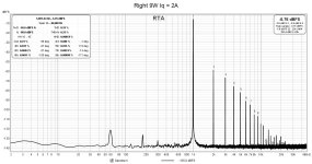
The second thing I did was to increase the JFET's Vds and thereby its Iq. I increased the gate voltage to the MOSFET until the current was 2 amps. The Hammond chokes are rated for 2 A. The resulting Vds for the left channel JFET was 3.44V and 3.24V for the right channel. The THD for each channel at 1W out to 8 ohms decreased a little bit from the previous bias setting.
Next, I wanted to see how much distortion would be at 0.5% to 0.6% THD into 8 ohms. Both channels were about the same at 12.4 watts.
I rotated the power transformer to try to minimize noise at the output and was able to drop the noise levels a small amount. Sound wise, probably not audible.
The second thing I did was to increase the JFET's Vds and thereby its Iq. I increased the gate voltage to the MOSFET until the current was 2 amps. The Hammond chokes are rated for 2 A. The resulting Vds for the left channel JFET was 3.44V and 3.24V for the right channel. The THD for each channel at 1W out to 8 ohms decreased a little bit from the previous bias setting.
Next, I wanted to see how much distortion would be at 0.5% to 0.6% THD into 8 ohms. Both channels were about the same at 12.4 watts.
Attachments
Hi
I prefer the distortion graph at 9W from your post 63 so I guess I’ll stick to 9W instead of 12W. Thanks for your hard work 😓
Thanks,
Eric
I prefer the distortion graph at 9W from your post 63 so I guess I’ll stick to 9W instead of 12W. Thanks for your hard work 😓
Thanks,
Eric
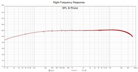
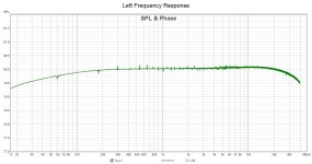
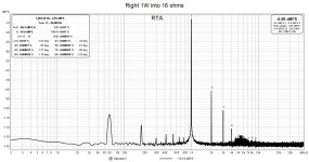
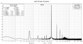
Next I did some distortion tests using a 16 ohm resistive load. I will be using this amp to power Quad ESL speakers so this is a relevant test.
I measured lower THDs with 16 ohm load compared to 8 ohm load. At one watt, the result is about one-third with 16 ohms (0.015%) compared to 8 ohms (0.045%). At 0.6% THD, the output power is down to about 7 watts into 16 ohms compared to about 12 watts into 8 ohms.
I'm listening the the amp (using choke loaded LuminAria preamp) now through my ESL 57s and I'm happy with the sound. I've got the preamp output maxed out, and the sound level is just right. It's in the Goldilock's zone; just right. But, I think some of my older CDs will need some more volume. A reason to build a small, full range speaker.
Another thing, there is no lack of bass using Hammond 159ZC chokes. I'm actually pleasantly surprised at the bass performance with the Quad ESLs. Overall, the sound is very fine. I'm used to listening to an all VFET/SIT system, and I don't miss having a SIT amp driving the speakers.
Attachments


I think if I made a measurement at 9W under the present operating point, it will be similar. I'll do that later.Hi
I prefer the distortion graph at 9W from your post 63 so I guess I’ll stick to 9W instead of 12W. Thanks for your hard work 😓
Thanks,
Eric

I have come to appreciate low distortion with dominant second harmonic too.
It would be interesting to see the distortion with your LuminAria providing the voltage gain, as that is what your listening impressions are based.
It would be interesting to see the distortion with your LuminAria providing the voltage gain, as that is what your listening impressions are based.
What I meant to say is I’ll use the operating point from your post 63.I think if I made a measurement at 9W under the present operating point, it will be similar. I'll do that later.
Thanks
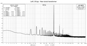
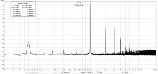
I have a set of measurements for my LuminAria that I made earlier this year with output of 1Vrms. So, at low output, the LuminAria has fairly low distortion. I don't have a measurement showing the LuminAria at high output voltage, but a measurement of the 2SK82 voltage amplifier stage that I use in my 2SJ28 source follower amp shows the distortion at 40Vpp. My choke loaded LuminAria circuit is based on this design and should be similar.
I would say the Quad ESLs, with their low efficiency, are a big contributor to the sound.
I would say the Quad ESLs, with their low efficiency, are a big contributor to the sound.
Attachments
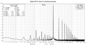
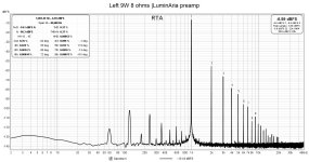
It's the combination of LuminAria and LD1014 follower that I am curious about. It would be interesting to see the FFTs of the two together.
I was interested in comparing the two operating points so I made the distortion measurements for 9W, 8 ohm output.What I meant to say is I’ll use the operating point from your post 63.
Thanks
The characteristics of the LU1014Ds vary from device to device so you will likely twiddle the potentiometer to adjust Vds to get the results that you want. DIY fun!
I found a magic combination of cable/wire positioning to get some low noise measurements.
Attachments


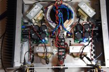
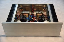
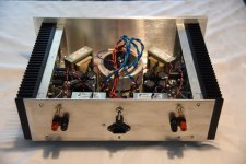
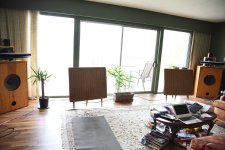
Some pictures of my 99% complete amp. I just need to drill the ventilation holes in the top cover plate and everything will be done.
Also, included is an amp family photo showing the LD1014D amp sitting on top of the 2SK182ES amp power supply (centre of photo). The other amps are all VFET/SIT based. The Quad ESL speakers (powered by the amp) and my biamped JBL speakers are shown in the other picture.
Also, included is an amp family photo showing the LD1014D amp sitting on top of the 2SK182ES amp power supply (centre of photo). The other amps are all VFET/SIT based. The Quad ESL speakers (powered by the amp) and my biamped JBL speakers are shown in the other picture.
Attachments

Looking at the LuminAria/LU1014 combination at 1W and 10W, the distortion levels are similar to my THF-51S Mu Follower Follower/DIY FE 2022 and 2SK180 choke loaded follower/DIY FE 2022 combinations. So perhaps similar sound too, just a different approach to achieving it. 🙂
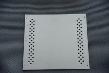
I drilled the top cover plate today and the amp is no longer topless.
I listened to it for quite while yesterday, and I am very happy with it. I am especially impressed with how it sounds with my Quad electrostatic speakers. I didn't expect 7W / channel into 83 dB/W/m 16 ohm speakers to work as well.
So, I'm ready to release this amp into the wild. A member asked me if I had a name for it, and I didn't. None of my amps have names, but then I haven't let any of my amps out to play, either. That got me thinking and I came up with a name: Little Loud Voice, or LiLoVo, or LLV. I felt that this was fitting since it is loud and powerful for the size of the SMD JFET, and it incorporates Lovo in the nickname.
For those who would like the PCBs, I am making the Gerbers available. Message me and I will send them to you. I am also open to ordering, say 10 pairs of boards, that I can send by mail to interested members. This could save a bunch of PCBs sitting around unused.
Attachments

- Home
- Amplifiers
- Pass Labs
- A Low Power Cascoded LD1014 Choke Loaded Source Follower