Hello, how you guys doing?
I had to dismantle my stereo setup and left all as it is, the BA3 and F4 working but somehow feeling not complete. With enough time to think about it the idea is to make the BA3 balanced (there already is a second PSU), I got a board and will only need to populate it and then add balanced outputs.
On the other hand my doubt is about how to make mono-bridge the F4 and make it balanced so that I can then have another one done and pull out 50W each.
My F4 was built dual mono so it has two transformers, if I recall correct 230VA each, if the project sees the light I'd want both F4 to be exactly the same, what is your suggestion, provided it is feasible, make the second F4 as the first, in dual mono fashion with twin transformers or swap the two for one and make things easier (but more expensive by swapping)?
Thank you

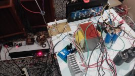
Yes, I am using a fairly large CRC supply with (8) 33,000 uF caps. I’ve also used CLC. Pretty beefy for a brute force analog supply.
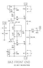
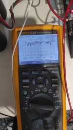
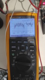
I put a scope differentially across the jfet drains and indeed see the power supply ripple (~4mv) at idle as expected. DC voltage about 27 from drain to drain. All as expected. With music playing the power supply noise signal becomes mixed with audio signal as expected with the passive mixer of bias and bootstrap signals. Ideally for lowest distortion and noise from a source follower circuit I’d like to see constant voltage gate to drain. I tried adding a 100 uF cap jfet drain to drain and it worked well. The drain to drain DC voltage stayed fairly constant even with the amp driven hard. I could no longer see any ripple voltage drain to drain with my oscilloscope. I don’t have any great tools to measure PSRR or distortion to verify any signal improvements, but from a jfet power supply noise perspective this looks like an improvement. Super easy to implement without removing boards, just tack solder cap from top of R6 to top of R7.
As a side note I also am using Exicon laterals with no source resistors and a LMV431 in place of the TL431 to enable lower bias voltage adjustment range for the laterals. If there is interest, I’ll post schematic and photos. Not sure if it belongs here or the F4 forum for comments.
I am working on an F4 + thinking of Exicon-double die ECW's ( 'nice' propietary pin layout - argh) + SMPS 10A + 4700µF + smallR + 56000µF +5mH + 2x56000µF = too crazy, too big, won't fit even in the box, the lid would not fit and no place for the driver. And I don't want to think out of the box. Instead. I'll have to go to the weight watchers.
- How do the laterals behave? How many do you have? How easy to set bias with the TL431? (difficult @ +400mV bias for 500mA/each side; I expect even a red LED with a resistor array works like the Dutch audiophile teams showed in the eighties)
I'm sure that 6L6 thinks: "however, after building pretty much all of the firstwatt amps, I know that they sound best with the recommended components"
Attachments
Last edited:
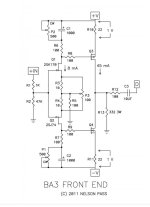
1. yes; BA3 amp is practically shown FE mated with OS functionally identical to F4; well, by memory there are 2 iterations of BA3 OS, and I'm speaking about complementary follower stage
2. yes, search for "crippled F4"
2. yes, search for "crippled F4"
Just finished my F4 and everything went well with no magic smoke being released. Ran the amp at 130mV for about an hour with everything stable, bias and offset. When I tried bringing the amp up to 200mV I could only reach 170mV. This is the same on both the left and right. The power supplies are dual mono and I’m using a 5U 500mm chassis.
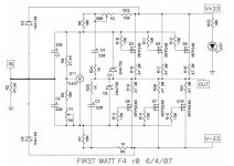
I’m thinking that I need to lower the resistance on R9 from 10k ohms to 5k ohms by paralleling another 10k resistor across R9. Please let me know if I have this fix incorrect.
I’m thinking that I need to lower the resistance on R9 from 10k ohms to 5k ohms by paralleling another 10k resistor across R9. Please let me know if I have this fix incorrect.
if you post or link your reference schematic, someone will confirm
matter of nomenclature and avoidance of broken phones effect
been there too many times
matter of nomenclature and avoidance of broken phones effect
been there too many times
I’m thinking that I need to lower the resistance on R9 from 10k ohms to 5k ohms by paralleling another 10k resistor across R9. Please let me know if I have this fix incorrect.
so, yes, proper thinking
though, take care to dial trimpot all the other way (adding its 5K) before powering up, so you'll practically have same Iq as when amp was powered off
Thank you for reminding me to dial back the trimpot. I knew I need to do that, but with my old brain I would probably have forgotten. Now it is ZM imprinted in my brain 🧠.

I paralleled R9 with another 10k resistor and the lowest I can get the bias is 200mV at startup and after an hour it settles at 229mV. This is in both channels. I could change R9 to a higher value but with all the cooling I have with heat sinks I’m not going to change R9. I may even increase bias to 300mV and call it done.
I did hook the amp up to a test system and everything sounds good. Now to connect it with some better gear.
I did hook the amp up to a test system and everything sounds good. Now to connect it with some better gear.
if you can get intended Iq, all good
300mV across 0R47 means 638mA, with usual 22V5dc rails, that's just 14.36W per device
6 times that, 86.17W per channel, in 5U/500, just warm
300mV across 0R47 means 638mA, with usual 22V5dc rails, that's just 14.36W per device
6 times that, 86.17W per channel, in 5U/500, just warm
The amp sounds very good. I don’t know why I waited so long to build one. That you NP for making this great design available, and the rest of the DIYA community for all the great help.
The amp is dual mono using Randy’s v8 power supplies and other pieces, as well as the matched Harris MOSFETS. In addition I added 50uF Ducati motor run caps.
The amp is dual mono using Randy’s v8 power supplies and other pieces, as well as the matched Harris MOSFETS. In addition I added 50uF Ducati motor run caps.
- Home
- Amplifiers
- Pass Labs
- A guide to building the Pass F4 amplifier