
Ok, will do. I've got the toshibas in there, so I'll just keep it as is. As always, thanks for the help and advice.

J2 sounds better to me than M2.
Not sure what you two are talking about, in M2 step up transformer goes after input jfets. As in vfet.
Ok, forget it.
Not sure what you two are talking about, in M2 step up transformer goes after input jfets. As in vfet.
Ok, forget it.
Jim, what you are saying i already did long time ago. My pre has step up on the output already.
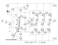
I was asking if anybody modified F4 as i draw. I guess not. I have F4 sitting idle and could try it. In M2, and VFET, its only one gate of output driven. In F4 its three pairs. Not sure step up can drive it.
I was asking if anybody modified F4 as i draw. I guess not. I have F4 sitting idle and could try it. In M2, and VFET, its only one gate of output driven. In F4 its three pairs. Not sure step up can drive it.
Not what I’m asking… if using a transformer for gain, why put it in-between the FE buffer and the output stage? It would have to deal with the input capacitance of the output stage as you allude to. If it’s in front of the buffer, the preamp will drive the transformer (easy) and the buffer will easily drive the outputs. I’m not sure what advantage, if any, would be had by putting it in the middle. If there is one, (and there certainly could be) I’d love to know.
How many turns? The transformer is trading off current for voltage so, as Jim is getting at, would have to figure out how much the drive impedance changes going into the output stage. Might be a better solution to put the transformer between the pre and the F4. I have no idea how much current headroom that buffer provides. Either have to calculate it or just try the experiment.
Ya I would say try it and see what happens. The impedance of the OS (tougher than M2 here as you already mentioned) is reflected back to the buffer, severity depending on the turns ratio. It may not like it. I know an autoformer sandwiched between buffers works great though based on my shenanigans these past few years..
We know that the F4’s buffer can drive the output stage to full swing, as that’s what it was designed for. Leaving it intact seems logical to me.
You could take a 1:4 transformer, example here https://edcorusa.com/products/pcw-s...8159419&pr_seq=uniform&variant=41236706623675
And that would increase the voltage of the preamp signal 4x then deliver it to the input of the F4 with no modifications, giving the voltage swing that F4 needs to make output power.
That same transformer could also be wired to provide a differential signal and bridge the F4 if desired.
I would like til build and use F4 with low watt tube integrated amp. But I am a bit puzzled over this set up. How do I connect 2 amplifiers together from speaker terminals on flea watt to RCA input on F4? What kind of cable arrangement is that? Can someone please explain, drawing/photo?

One other thing. Can I substitute F4 with MoFo in the schematic above since both having no voltage gain?
- Home
- Amplifiers
- Pass Labs
- A guide to building the Pass F4 amplifier