
Caveat: Others like @Dennis Hui and @Zen Mod are may more versed at troubleshooting than me.
Q corresponding to R18 is running a bit hotter but otherwise the triplets seem to be functioning in family.
How many turns are you making on P2?
Q corresponding to R18 is running a bit hotter but otherwise the triplets seem to be functioning in family.
How many turns are you making on P2?
Lots of pictures are helpful.
How are you hooking up the DMM?
You mentioned replacing the pot. Does the old one measure fine?
How are you hooking up the DMM?
You mentioned replacing the pot. Does the old one measure fine?
Problem solved, it was my fault. 🤢🤣
After much inspection I realized that I had swapped the minus rail and GND wires on one channel. Lucky I didn't fry anything. I just started both channels and adjusted the bias and offset. Thanks to everyone who helped make this a success and happy new year!!!🙂🥂
After much inspection I realized that I had swapped the minus rail and GND wires on one channel. Lucky I didn't fry anything. I just started both channels and adjusted the bias and offset. Thanks to everyone who helped make this a success and happy new year!!!🙂🥂
I am looking for a unity gain current buffer for my tube preamp to drive dynamic headphones (24 to 70 Ohms with 102db sensitivity), curious any one using F4 for this purpose by chance or see issues using for this purpose?
Ideally F2 might be more than enough, but don't see any kits to attempt building it with my skills. I do see few DIY kits for headphones specific but they all add some gain and then they all have volume controls, trying to use my pre volume control and simplify the approach via a good current buffer as a power amp, appreciate the thoughts.
Ideally F2 might be more than enough, but don't see any kits to attempt building it with my skills. I do see few DIY kits for headphones specific but they all add some gain and then they all have volume controls, trying to use my pre volume control and simplify the approach via a good current buffer as a power amp, appreciate the thoughts.
To play at 110 dB sound pressure level (which is ear-splitting loud), your 102 dB sensitivity headphones need a drive signal whose voltage is 2.5V RMS (7.1V peak-to-trough) and whose current is 105mA RMS (for 24 ohm headphones) or whose current is 36mA RMS (for 70 ohm headphones).
That's a tiny fraction of what the F4 audio power amplifier can deliver.
I suggest going WAY smaller: Lay out your own PCB using just a dual opamp IC and a pair of BUF-634A current buffer ICs. Opamp and BUF are connected as a unity gain composite amplifier -- a "current buffer". Distortion will be tiny thanks to the opamp performing error-correction upon the BUF's transfer function, all inside a single global feedback loop.
The BUF634A can deliver +/- 250 mA, which is more than enough. And if you use +/- 15 volt power supplies your unit will have more than enough voltage swing.
You'll have loads of fun, doing circuit design and PCB layout before assembling the final unit!
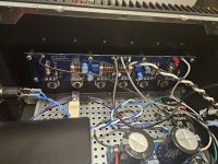
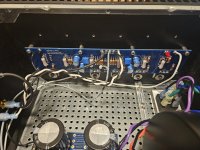
Finished my third FirstWatt diy build today. My first build was an M2X, and the second was an Aleph J. I’ll call this one my ThirdWatt.
It’s a standard build using the diyAudio Store F-4/BA-3 Transistor Kit, which are said to be matched, however I received mine without any values marked on the mosfets. But I decided to charge ahead and installed them anyway.
Shorted the inputs and adjusted voltage across R16 to 0.13v and let it cook for an hour. Readjusted to 0.2v, and offset to zero (+/- about 1.5mV), and let it cook for another hour with the cover on. Here’s the measurements across all of the source resistors after the last hour:
Left Right
R16 .206v .205v
R17 .215v .196v
R18 .221v .194v
R19 .201v .213v
R20 .235v .201v
R21 .205v .183v
Are these values acceptable? Would there be any benefit to making any changes?
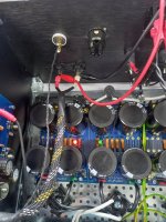
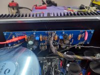
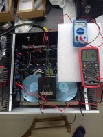
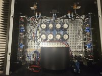
Attachments
count in triplets;
one N triplet, one P triplet per channel
if you're in 5% in triplet, perfect
if you're in 10% in triplet, still good
if you're in 15% in triplet, acceptable
more than 15%, think about tighter matching of mosfets
one N triplet, one P triplet per channel
if you're in 5% in triplet, perfect
if you're in 10% in triplet, still good
if you're in 15% in triplet, acceptable
more than 15%, think about tighter matching of mosfets
Thanks ZM. Unfortunately, it looks like the P triplet on the left channel is just outside of acceptable range.
(.235 + .201) / 2 = .218
.235 - .201 = .034
(.034 / .218) * 100 = 15.59%
Looks like I'll have to make some changes.
(.235 + .201) / 2 = .218
.235 - .201 = .034
(.034 / .218) * 100 = 15.59%
Looks like I'll have to make some changes.
Triplet is 0.201, 0.205, 0.235. Average is 0.214.
0.235/0.214=1.10, or 10% high.
0.201/0.214=0.94, or 6% low.
So just within 10%.
At least that is my interpretation.
0.235/0.214=1.10, or 10% high.
0.201/0.214=0.94, or 6% low.
So just within 10%.
At least that is my interpretation.
Right channel voltages also have a big spread. What if R19 are swapped.
It will then be 0.213, 0.235, 0.205, and 0.201, 0.201, 0.183.
Numbers will be a bit different after re-biasing,
It will then be 0.213, 0.235, 0.205, and 0.201, 0.201, 0.183.
Numbers will be a bit different after re-biasing,
What if R19 are swapped.
similarity between two groups is by setting, not by initial equality of Ugs
so, no elements to count of interchangeability, if sameness isn't established by Ugs value
- Home
- Amplifiers
- Pass Labs
- A guide to building the Pass F4 amplifier