If it has a german plate sayin M-ZM, maybe?
(I was behind it and before I could take a pic another car—of wich the color I don’t remember—got between us.
And me, yes, life was good with me, I went to Salas‘ universe, and turntable restoration.🧐 (business is a bit rough at the moment)
(I was behind it and before I could take a pic another car—of wich the color I don’t remember—got between us.
And me, yes, life was good with me, I went to Salas‘ universe, and turntable restoration.🧐 (business is a bit rough at the moment)
Hi everyone,
I am making this amp right now.
I received all the parts I needed so far, excepted one!
I have few questions regarding the power supply schematic presented at the very first post of this thread.
I live in Australia, therefore I am doing the 240 volt version of the power supply.
My questions are around the 0.033 "LINE" capacitor linked to the primary of the transformer:
1- I belive the value is 3.3nF, isnt'it?
2- It's voltage should be at least 350V, isn't it?
3- What is its function? Correct me if I am wrong (my notion of electronics are limited), I have the feeling that it buffers most of the current surge when the power supply is switched on, in order to protect the electrolytics capacitors downstream. Am I far away
4- How is it critical for the circuit?
Regards,
JD
PS: I have been following this forum for quite a while and I belive it is my very first post. Thanks for having me!
I believe it is to clean a little high frequency noise off the AC line. As it is across the line it should be a class X1 (best) or X2 (OK) rated capacitor. These fail safe, you don't want to burn your house down! The value on the schematic is 33nF but the value isn't critical, you can omit it and the PSU will still work.
Last edited:

The capacitor should be a X class and is for filtering high frequency hash on the the AC line. It is not for surge suppression, that's what the thermistor is doing. It depends if you have dirty AC if the cap is needed. I don't always use the cap but you'll want (need) the thermistor or some other soft start.
Thank you so much for your help and explanation Simon Dart and ZUM911.
Thanks to you, I learnt a bunch on the safety cap and their different class and use. Great!
I will use the thermistor for sure.
Thanks to you, I learnt a bunch on the safety cap and their different class and use. Great!
I will use the thermistor for sure.
Please help, if anyone is willing. Are these good mosfets for building f4 amps? bought in diyaudio store.

A couple of years ago when I made my first f4 I used these, also bought in the diyaudio store


A couple of years ago when I made my first f4 I used these, also bought in the diyaudio store
I assume IRFP140 is N channel and IRFP9140 is P channel. Will there be a big sonic difference between the left and right channels when I run both amps as monoblocks, since each monoblock has a different type of mosfets?
I assume IRFP140 is N channel and IRFP9140 is P channel. Will there be a big sonic difference between the left and right channels when I run both amps as monoblocks, since each monoblock has a different type of mosfets?
That’s not how it works.
Each F4 PCB needs three N-channel and 3 P-channel.
How you utilize those assemblies later, Stereo amp, Parallel mono block, Bridge monoblock, has nothing to do with the fact that each F4 PCB needs three of each N and P.
^ I think you and @simon dart are assuming the same thing... that they're talking about using the N's on one channel of a stereo F4 and the P's on the other.
What I think @skrifa is asking is if when using (properly) the 9140s and 140s vs. the 9240s and 240s from their previous build... will those two amplifiers when used as left and right channel monoblocks... sound any different?
Edited to add... looks like Simon deleted their post.... so... ignore that reference.
Ah! Good point.
No, it’s not going to make much, if any difference, as the “sound” of F4 is 98% the preamp driving it.
No, it’s not going to make much, if any difference, as the “sound” of F4 is 98% the preamp driving it.
running F4 monsterblocks with balanced input, they are very, very neutral. So neutral, I'm building various preamp circuits as stand-alone front-ends/gain stages to play with flavor. Although, I have to rethink this as, after moving, the listening space is much smaller and the Benchmark DAC will drive them quite handily into hurty volumes.
Attachments
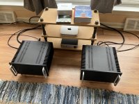
Ok, it's hard to understand my English, but yes @ItsAllInMyHead was right about my question and now I have an answer. Thank you all..., however, I have more questions. My first f4 was made a year and a half ago as a dual mono amp and it sounds great with a ba-3 preamplifier and a small 4.5w tube, but it lacks a little volume with my 83db sensitive speakers. I have now acquired all the parts for another dual mono amp to run both first as parallel monoblocks and then as bridged monoblocks. do you think it could work that way? I hope you understand my question. Here is a picture of my first f4 amp, currently disassembled to add a balanced input
Others are more knowledgeable but my biggest question in running the dual PSUs is how close do the rails measure from left to right channels? Maybe the better questions is how much offset between +left and +right speaker outputs?
Yes. See the user manual for how to connect them if you've wired yours like a factory unit.I have now acquired all the parts for another dual mono amp to run both first as parallel monoblocks and then as bridged monoblocks. do you think it could work that way?
https://firstwatt.com/pdf/prod_f4_man.pdf
@skrifa Volume/listening level has nothing at all to do with the F4 and everyting to do with your preamp. If you want it louder, the only thing that will make a difference will be a different preamp that has more gain. Monoblocks will not change the volume. The F4 has no voltage gain, all the gain is in the preamp. You need more gain, not more power, and the only place to change it is in the preamp or possibly in your sources.
That said, if your speakers really are 83db, monoblock is a good idea.
@6sX7 doesn’t matter, as the offset will be zeroed at the amplifier.
That said, if your speakers really are 83db, monoblock is a good idea.
@6sX7 doesn’t matter, as the offset will be zeroed at the amplifier.
@6L6, I need to sit down and think this thru. I had thought about going dual PSUs in mine but wasn't sure if there were deltas between the two PSUs on the rails, how much it would affect the operating voltage points between the left and right boards. Probably overthinking it but the thought did occur.
If his preamp has balanced outs and depending on the specs compared to single-ended outs, the extra voltage swing might do the trick?
If his preamp has balanced outs and depending on the specs compared to single-ended outs, the extra voltage swing might do the trick?
- Home
- Amplifiers
- Pass Labs
- A guide to building the Pass F4 amplifier