The SLB is a cap multiplier and will drop a few volts more than a CRC will. I wouldnt use a plain CRC with 22V mains xformers
I agree with the above. The JFet input stage of the F4 needs to be handled with some care.
On the other hand, the SLB supply boards will yield about 26.5V from 22V mains transformers. My F6 runs like this. The F4 input stage should be Ok with 26.5V rails.
On the other hand, the SLB supply boards will yield about 26.5V from 22V mains transformers. My F6 runs like this. The F4 input stage should be Ok with 26.5V rails.
Yay! 🤓
I have successfully finished building my first F4.
The #%@& metalwork aside, it was plain sailing. I did change R8 to 27k before mounting everything though.
I have been listening to it for a couple of days now, and it is hands down the best power-amp I have ever heard!
Totally transparent and in control. The GRIP this thing has on the speakers is quite simply phenomenal.
My reference in this regard, is a pair of pretty hefty monoblocks from the 80's, with the power to weld, and I honestly never thought I would ever listen to anything that would surpass these.
Well... now I have!
I cannot thank you all enough for making this possible. Papa for sharing your brain, and to all of you guys at diyAudio for making it possible to realize. THANK YOU!
Now... I do of course have ONE question:
Bias is set to 50C on the sinks, and I measure 210-230mV on all 6 critters in one channel.
On the other channel i get 170-190mV on 5 of them, and 285mV on the last (a Harris).
Is this a normal/acceptable spread or something I should worry about? I bought the kit from the diyAudio store.
Once again... thank you all!
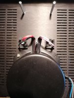
Attachments

I had similar experience. A couple of the output MOSFETs were current hogging. Offending channel had some obvious distortion at the loudspeaker when cranked. Replaced with match sets from ThatcherDIYAudio and it cleared up. https://www.etsy.com/listing/958609584/first-watt-f4-ba2-ba3-mosfet-kit?click_key=e808c32ad9c50c5c2d8776c3f87b822da191015d:958609584&click_sum=367b272d&ref=shop_home_recs_6
Another option is to swap the 285mV for the 210mV and see if it is any better.
Others (like @Zen Mod , @Dennis Hui) where a big help in diagnosing my amps so hoping they can chime in.
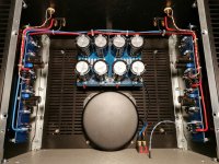
Very nice, super clean layout, btw.
Another option is to swap the 285mV for the 210mV and see if it is any better.
Others (like @Zen Mod , @Dennis Hui) where a big help in diagnosing my amps so hoping they can chime in.
Very nice, super clean layout, btw.
Nice build.
Just wondering about the distribution of the voltages between the N and P channel mosfets in the bad channel. Assuming 3 x 190mV on one side and 2 x 170mV + 285mV on the other side, they are not equal. What offset do you measure at the output?
Please measure again and post the individual voltages. Perhaps moving some mosfets around may help the situation.
On the other channel i get 170-190mV on 5 of them, and 285mV on the last (a Harris).
unacceptable
replace entire triplet where you have that one showing 285mV, with matched triplet
no need to replace other polarity triplet
now, all that if you're sure that soldering is OK, resistors are proper (value) and that measurement is OK (what Ben said )
Definitely!Yay! 🤓
It's not 'normal', but if you've mixed one Harris part with let's say Vishay or other in the other 2 positions ... it's expected. I believe the Harris parts are known for having a slightly lower Vgs (it will turn on at a lower voltage and allow more current to flow at the same voltage). Not sure if that's accurate for your situation. Overall, the N channel parts are supposed to be matched for Vgs within each channel as are the P channel parts.Now... I do of course have ONE question:
Bias is set to 50C on the sinks, and I measure 210-230mV on all 6 critters in one channel.
On the other channel i get 170-190mV on 5 of them, and 285mV on the last (a Harris).
Is this a normal/acceptable spread or something I should worry about? I bought the kit from the diyAudio store.
Can't be certain until you provide measurements for each of the others and clarify if you just used that one Harris part in that one position or not... Until then, just speculating re: that one part.
Either way, congrats on an excellent build. As you've noticed, the F4 is special.
Edited to add - Ben and ZM are always more credible... and definitely faster typers. Listen to them. 🙂
Thank you all very much for your kind replies.
Everything is quadruple-checked, and I did actually swap 2 of the Harris' to be sure I didn't mess up somewhere.
One of the Harris' is definately drawing more current, I just wasn't sure if it was within what could be expected from a matched set.
As ZM says it's not, would it be reasonable to ask the diyAudio store for a new Harris triplet?
Perhaps if I bought something else from the store, they wouldn't have to spend anything on shipping!?
🙄
Does the FET have an ID number? Maybe it can help the Store to find/solve your issue.
Quoting from the Store:
Quoting from the Store:
Any numbers on the MOSFETs are ID numbers only, and are not related to their measurements nor their matching
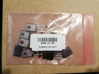
If it is not too much of a PITA, could you take some pictures of the case markings (mfg case markings) of the FETs.
It seems unusual (to me, but others may know better) that there would be two manufacturers within the same N or P channel MOSFETs. I may have misunderstood you previously though....
If they're the same product and matched properly (which should be the situation) then the issue is likely with your build. If they're not the same... then it is not certain, but it could be that the FETs are not matched to Vgs and it's just a simple mistake in your parts.
Either can be fixed, but it would be great to rule out any issues with assembly also. It would be a shame to get new matched FETs and have the same or a similar issue.
Yes, I have checked all resistors both visually and by measuring (multiple times).
The small ones are Dale RF55's and they are all spot-on. The big ones are Panasonics, AFAIR.
I have also moved the offending Harris, and the current draw follows this particilar one.
There is NO doubt that one of the Harris' is drawing more current than the rest.
I just wanted to know if the difference was enough to worry about, and since it is, I will get a new matched triplet.
Thank you.
Last edited:
picture speaks zillion
we still don't know state of facts - do you have all same manufacture parts in each triplet?
we still don't know state of facts - do you have all same manufacture parts in each triplet?
Send me your shipping address and I'll send you the Harris triplet.


Hello,
This is Carlos, I've been reading/enjoying this post for a while, hope that you guys are great.
I am currently assembling an F4, I have tried before the F6 and currently running on an Aleph J with JBL L300 speakers and an EAR phono preamp
I am building the F4 because I want to try to use a single ended tube amplifier (valve 45 RCA, approx. 1.5 Watts) with the L300...
At this point I am building only one stereo F4 to see how this goes.
Some questions:
1) What brand/type of resistor is best for loading the tube? Is a wirewound resistor OK? what has given you good results? should I try different values? 8ohms, 16ohms, 32ohms? The amplifier is meant for 8ohm speakers.
2) Does this make sense? 45RCA tube single ended loaded with 8ohm wirewound resistor to F4 to JBL L300? Is one F4 enough for the L300?
Cheers,
Carlos
BC, Canada
wirewound in metal case (chassis mount) 25W or more
try 8R and double that - 16R, for higher level
leave in what you prefer more
of course other types (MOX, metal plate) are better but in practice any resistor is cleaner and more benign load for amp, than speaker is ...... so you'll hardly hear difference
power of said resistor is more important than exact type
if needed - you can insert autoformer (repeater accordingly connected, Edcor, Cinemag, Jensen) in front of F4, to up signal even more
- Home
- Amplifiers
- Pass Labs
- A guide to building the Pass F4 amplifier