Easy to build and measure. Let us know stretchneck, I’m curious as the BA-3 has been on my sights for a while. The F4 gives us endless possibilities. At first I thought about making an ‘integrated F4‘, i.e preamp within F4 but now, I think I’d rather have a ‘solid state voltage gain stage box’ with a +/- V power supply where I can pop in/out various linestage topologies, i.e. Wayne’s BA2018, BA3FE, DIY2022FE, X’s Aksa Lender, etc…
Coda’s system 1/2 is basically a single box that contained a gain/Vas stage and then another pair of boxes with source follower topology amplifiers. It’s a great idea and F4 can be adapted as such. The modern one is now called S150/250.
Sorry for rambling…all is possible for the FAB network!
Best,
Anand.
I looked at the Coda set up... GULP.... the SV is pretty expensive. How different is it from just getting a couple of autoformers?
My current goal is to drive a pair of F4s with a BA3 based preamp -with balanced outputs. I did buy the Elcor transformers that I will try with my B1K... I think that will be enough voltage swing, but that is just a toy... truly I need a preamp with more inputs, balance control and a tape monitor...
In post #1 6L6 mentions that there is a typo on the original schematic (not sure what). My F4s date back to 2007 and used Peter Daniel’s boards. Does anyone remember whether those boards used a corrected schematic?
Peter's boards came with the attached schematics which came in an earlier version of the F4 document. The only typo I noticed was the part number for D1 and D2.
I didn't see any real difference between this and the schematics in post #1. (I only looked dquickly though.)
The current F4 manual has a slightly different schematics (source resistor value for the jfets and gate resistors for the mosfets), but nothing dramatic.
(https://www.firstwatt.com/pdf/prod_f4_man.pdf page 13)

Ah...forgot about R8, which is useful if the mosfets need more Vgs.
In this case, it sounded like Studley's build from 2007 is OK with the earlier schematics.
In this case, it sounded like Studley's build from 2007 is OK with the earlier schematics.
Last edited:
Sorry to say I'm no able DIYer, but I have always wanted to know if there was ever a full set of distortion measurements done on a stock F4.
That is, distortion vs. output (8, 4 ohm loads), distortion vs. frequency-at least from 70Hz and up (not just at 1kHz), et al.
That is, distortion vs. output (8, 4 ohm loads), distortion vs. frequency-at least from 70Hz and up (not just at 1kHz), et al.
I think ASR looked at a diy version. They bash anything that's not dot million zeros distortion, so keep that in mind. It's "entertainment not dialysis" in this neck of the woods..
Anyone considered trying 'Super E capacitor configuration' (Mount two non-polars parallel to each other, each in opposite direction (fake-minus to plus and vice-a-versa) for the caps on F4?
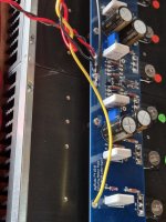
I got my F4 up and running today, temporarily lashed up. With 20V rails, 200mV across the source resistors and a 4U 400mm modushop case, I seem to have a fair bit of thermal headroom. Are there any downsides to cranking up the bias a bit more? I have 4ohm LS50 speakers.
Attachments
Run 'em hard, run 'em hot.... heatsink at 50C at thermal equilibrium under worst case conditions is a reasonable target. And very very definitely no higher than 55C.
Please allow me to ask, I have a spare 2pcs of antek 500VA 2x25V and can I use mono firstwatt F4 ,instead of original volt 2x18V .
2x25V will be fine, once you account for losses from rectifier and resistor in a CRC then you'll be about on target.,
2X32V DC loaded, including losses... or thereabouts... is that okay for an F4? I'd expect that to be...
Last edited:
Hello stretchneck ,
You mean change resistor value ?
Original is parallel 3watt .47 ohm and Which value will be replace ?
Thanks
You mean change resistor value ?
Original is parallel 3watt .47 ohm and Which value will be replace ?
Thanks
I wish all threads on DIY audio would start with clear guidance on supply voltage, otherwise you end up digging around the thread to find it.
My configuration will be:
https://www.diyaudio.com/community/...ing-the-pass-f4-amplifier.234355/post-7289754
F4, just like BA3, is 24vdc to 32vdc. @Extreme_Boky will be pushing thermal limits.
I can't advise on resistor to use in CRC, you'll need to do your research and work out what works best for your target voltage / ripple. You could use PSU Designer.
In addition to the thermal, one should consider the Vds of the jfets as well. With +/-32V rails and, say 7mA current through the jfets, even without an input signal, the jfets are at near 25V, which is what the 2sj74 is rated at. This will modulate with an input and can swing well into the 30s with a large-ish signal.
- Home
- Amplifiers
- Pass Labs
- A guide to building the Pass F4 amplifier