All that one needs to know is to get a TL431 with a minimum current requirement less than 300 uA. That's 0.3 ma. That is what Papa posted as the threshold for proper operation given a stock build, i.e., following the FW schematic. It also assumes that you have BL grade JFETs.
If you have already built something, just measure across the anode and reference of the TL431. If it reads 2.5 V, you are good to go. If it is less than that, it should be replaced. There are more convenient places to measure than the legs of the TL431, just look at the schematic. It is tight in there, so be careful. Last thing you want is to go in there and short something.
If you have already built something, just measure across the anode and reference of the TL431. If it reads 2.5 V, you are good to go. If it is less than that, it should be replaced. There are more convenient places to measure than the legs of the TL431, just look at the schematic. It is tight in there, so be careful. Last thing you want is to go in there and short something.
I just completed my second F4. The first one worked but second does not. The LEDs didn't light. I found the plus side of the power supply wasn't working, so I fixed it. Now the LEDs light but I get no bias voltage. Was it damaged from powering it up without plus power?
An externally hosted image should be here but it was not working when we last tested it.
An externally hosted image should be here but it was not working when we last tested it.
Is there a defective component that would cause this?
My images aren't loading for some reason. I'll keep working on it.
Last edited:
It's the schematic on first page of this thread. I clicked upload file from your computer, but nothing happened.
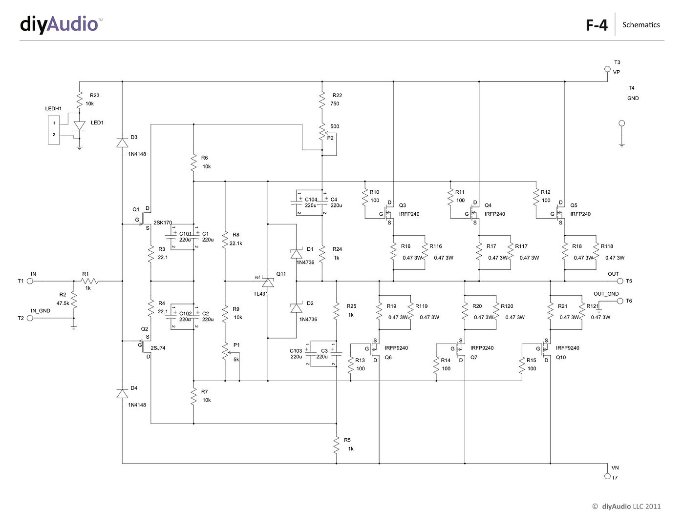
measure voltage value you're getting across TL431, with min and max setting of P1
if in doubt where to put probes - gates of upper and lower mosfets
of course, keep DVM across source resistors to track Iq, just in case
sch is easy - first post schm - right click - "copy image address"
click on image button above text frame here, paste image address in address field
it looks like this (damn photobinsandbuckets):
compare positioning/orientation of parts with your working one
you didn't specify, but I presume - you're having same problem with both channels ?
for start replace TL431
plenty of info in last posts which ones are OK, which one to avoid
you didn't specify, but I presume - you're having same problem with both channels ?
for start replace TL431
plenty of info in last posts which ones are OK, which one to avoid
Both amps are identical, and I really took my time soldering the boards since I was waiting on parts. Yes, both channels. I'll try replacing the TL431s. It seems weird both are defective. I got them from the DIYstore.
if you have expected voltages at drains of input JFets ( outer sides of biasing network 10K resistors) then TL431 is culprit- eating excessive current , so voltage sag is way too much and regulation is non-functional
where you bought your JFets?
where you bought your JFets?
I was measuring the wrong terminals on the TL431. I'm getting 2.49V from anode to ref.
I got my JFETs from alweit on eBay
I got my JFETs from alweit on eBay
Just measuring anode to reference is not necessarily the best measurement by itself to make.
Depending on the bias requirements of the output stage it's actually possible to measure 2.5V purely by chance and not due to the zener actually working.
It's important to guarantee correct operation you're measuring 12.5V bare minimum across the 10k resistors, if you are using TL431
I haven't seen your previous posts.
This is just something everyone should realise, so thought I should mention it.
I measured 15.8V on one channel and 16.6V on the other. I can't help thinking the power supply malfunction had something to do with this. I built a preamp a few months back, and it worked fine until the power supply failed. When I hooked up a new power supply, the board was toast. I wound up scrapping it. It just seems so unlikely I would have two defective TL431s.
They don't need to be defective.
There is a long winded discussion around the issues of TL431 used in this circuit. If you go back and read it, hopefully it will all make sense.
I don't want to have to repeat it all.
Just a few pages back.
It's worth understanding this even if it's not related to your problem.
There is a long winded discussion around the issues of TL431 used in this circuit. If you go back and read it, hopefully it will all make sense.
I don't want to have to repeat it all.
Just a few pages back.
It's worth understanding this even if it's not related to your problem.
^ OK, thanks. After reading page 215, I see I ordered the wrong ones. Oh well, more shipping charges.
Mounting the transistors: Thermal connection...
Hello again.
I'm kinda thinking loud. May I ask to interfere if it leads me to a wrong/inferior track?
About the thermal connection of the transistors:
Usability aside, what is better to use:
Keratherm (W/mK 6.5)
Aluminum Oxide Ceramic #4180G (15.06W/m°C at 75°C)
Silpad TSP 1600S (3.41 C/W @ 25psi) …
While Diyaudiostore is raving about Keratherm (usability and performance), the numbers suggest Aluminium Oxide, and the Silpads, well, seem not suited for a class A...
I'll go with the unknown Aluminium Oxide.
Keratherm, Aluminum oxide + Thermal goop
Thanks ZM!
Is it transistor-goop-aluoxide-goop-heatsink?
Thank you ZM and 2 picoDumbs for your reply's.
I replaced the TL431s with NCP431s and it still doesn't work. Any suggestions?
This reminds me of the time I had an open frame headphone amp where a moth flew into it and shorted it out. I replaced every semiconductor and it still wouldn't work. I wound up throwing it out. I'm thinking I may have to scrap these boards and start over.
- Home
- Amplifiers
- Pass Labs
- A guide to building the Pass F4 amplifier