Thanks 6L6 and Andrew, you are very helpful. My first big amp so a bit nervous to burn everything (;-)
In Newnan . I got a 1000va Antek . and working on 460,000 mfd total with chokes in the power supply . Have not fired it up as of yet. Also dedecated 20amp lines for the amp and front end . Using a p300 for regent on the pre and turntable and digital .
Trio,
use a mains bulb tester to power up the transformer.
Power down and connect the rectifier.
use a mains bulb tester to power up the transformer + rectifier.
Power down and connect the smoothing caps.
use a mains bulb tester to power up the transformer + rectifier + smoothing caps.
use a mains bulb tester to power up the transformer.
Power down and connect the rectifier.
use a mains bulb tester to power up the transformer + rectifier.
Power down and connect the smoothing caps.
use a mains bulb tester to power up the transformer + rectifier + smoothing caps.
please no smoking
Hello again,
Back on October 18th post #387 p39 I posted about a runaway bias issue. It looked like I may have let some contact happen between MOSFET and heat sink because only one MOSFET had superheated. I ordered new triplet of MOSFETs, installed and got my right channel (the one without problems) tuned up then tried the left channel with the new MOSFETS.
I came on (with the bulb tester) higher (more voltage across a 0.47 source reisitor, 125mV as opposed to 50mV on the good or right side) than the other channel. It seemed to stabilize though. While I was adjusting the P2 pot for offset (which had not effect by the way) it shot up to twice its innitial value so I shut the thing down.
So, it was not a bit of metal that fried the first MOSFET. Something is amiss. From what I have reported so far is there a prime suspect?
I know these things are hard to figure out.
I can and will depopulate and check the entire board if necessary but I wouldn't mind starting with the usual suspects.
bias circ is first suspect
replace resistors around TL431 and TL431 also , recheck pots , replace if they're suspect
replace resistors around TL431 and TL431 also , recheck pots , replace if they're suspect
naughty little TL-431
Swapping in a new TL-431 did the trick!
I checked all the surrounding resistors while I had the board on the operating table but it was just that silly little three legged frustration device. I recommed everyone to buy the Texas Instrument version as it has tighter specs...
Now that all is well I'm stupidly going to ask: can I add a few LEDs to light my front pannel? How best to do this, draw directly from the 24+/- power supply?
The LEDs I'd like to use (4 of them) have a FV of 3 to 3.4 and draw 24mA...
what's wrong with FW approach ?
it's so stupid simple - resistor fed from positive rail , then to gnd

don't let them soak more then 5mA , you can go blind
it's so stupid simple - resistor fed from positive rail , then to gnd
don't let them soak more then 5mA , you can go blind
Oh there's nothing wrong with FW!
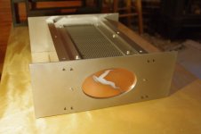
I just don't know the ramifications for tapping the supply. I really need some brightness as I am not just putting in an indicator but lighting a opal piece of plastic from inside the case. I need 4 LEDs at at least 12mA. See photo for fugly front piece...
I just don't know the ramifications for tapping the supply. I really need some brightness as I am not just putting in an indicator but lighting a opal piece of plastic from inside the case. I need 4 LEDs at at least 12mA. See photo for fugly front piece...
Attachments
Why not use the LED positions on the F4 & PSU boards, just run wires to extend them out to where you want them. Also if one dosent light you will know which PSU or Board isnt working ;-)
Stock BOM lists a 10k resistor feeding the LED, can be modified to suit the needs of whatever LED's you are using to get the brightness you need.
Indication is that if I dropped 10K to 1K (.25W) I could run 4 LEDs in series at 12mA off each board. I just worry about if this alteration will mess with the F4 as designed...
Am I being silly?
Am I being silly?
blue and white LEDs have a higher Vf expect ~3Vf
All the others, from IR to orange are generally <2Vf
Subtract the Vf from your supply.
Divide the remainder by your desired current to give the current limiting resistance.
i.e.
[24Vdc - 2Vf] / 0.003mA = 7333r, use either 7k5 or 6k8
All the others, from IR to orange are generally <2Vf
Subtract the Vf from your supply.
Divide the remainder by your desired current to give the current limiting resistance.
i.e.
[24Vdc - 2Vf] / 0.003mA = 7333r, use either 7k5 or 6k8
Hi Andrew, super guy with engineering data 🙂
I'm completely out of my depth here so it is as if I am superstitious: I'm hoping to draw at least 12mA not 0.003mA. I need to tap a not negligible amount of power off the PSU or so it seems to me.
I'd like to run 4 blue LEDs (FV3.2) / channel (in series) at 12mA. Calculations from Quickar indicate a need a 1K 1/4W resistor instead of the standard 10K (in position R23 on the F4 schematic I have). Will this have a deliteroius effect on my amp or am I just a sissy?
Attachments

The light will be diluted/diffused through a thick opal plexiglass, only the portion exposed by the impala cutout (see previous post and pic) will show into the room 🙂
I'll give it a try 😛
I'll give it a try 😛
ooooops, the m in 0.003mA should not be there.
Using 3 or 4 LEDs in series is OK if you have sufficient voltage to drive the lighting circuit.
But do take account of varying supply voltage. Is it 24Vdc +-0.5V, or +-1V, or +-1.5V?
Calculate your resistor for the nominal voltage. Check at minimum voltage and maximum voltage, checking maximum current does not blow the LEDs nor overheat the resistor and checking minimum current actually turns on the LEDs.
- Home
- Amplifiers
- Pass Labs
- A guide to building the Pass F4 amplifier