Hi Elbert I use this online one 🙂 THD to dB - convert percent to decibels dB and dB decibels to percentage percent voltage % vs per cent converter THD+N distortions calculation signal distortion factor attenuation in dB to distortion factor k in percent decibel damping - sengpielaudi -17db is about 0.028% THD
Also I use RMAA for doing distortion analysis of my amps. It's only as good as your sound card (test it first with loopback cable to get a baseline), but it is good for doing comparisons of before and after changes! Here is an example of testing my chipamp with it. RightMark Audio Analyzer test: gc4 Note that I've canceled that ISP service so I'm surprised it is still there, so it will disapear at some point. That measurement was made before I made an earth loop breaker for the mains connection. Any measurements you do with a pc will likely result in 50Hz noise (and harmonics) due to an earth loop created between the pc and the amp, since they will both be connected to safety earth.
Tony.
Tony.
Last edited:
Hi Tony,
Funny, I just stumbled across that very same calcualtor some 15 minutes ago, but thanks a lot anyway! 🙂
HolmImpulse has a calibration feature for use with a loop-back connection.
I'm using a laptop for measurements by the way, so ground loops should not be an issue.
That RMAA software looks interresting.. seems its primarily intended for checking the sound-card of PC's but of course, if you stick an amplifier in the loop, it will obvilusly measure that as well, clever... 🙂
I do get some bizarre results at the moment, so I guess I need to play around with the output/ input levels, and make a proper screened cable with clips so I can inject test signals directly in to the amplifier card inputs bypassing the x-over card..
Please do try using ARTA and STEPS. STEPS will give you outputs in both dB and %. ARTAs spectrum analyser works only in % but you can easily drag the cursor over specific harmonics if you wish to know their level.
0.028% sounds like there's something very wrong going on, but from what you've said it seems you need to get a loop back working correctly first. The Dell laptop we've got will give distortion around 0.005%
0.028% sounds like there's something very wrong going on, but from what you've said it seems you need to get a loop back working correctly first. The Dell laptop we've got will give distortion around 0.005%
Yes, don't pay too much attention to that 0,028% figure yet.. I'm still messing arrond a bit..
First, had to set both output and input on the laptop to get the right balance, and then I did a loop-back..
The THD after loopback was between -80 and -70 dB for the sound-card, and when I did the amps, I got arround -75-80 dB THD curves (-80 dB = 0,01%)
According to the specs provided for the amps in the Elektor magazine article, this is not where it should be, but it would seem I have limitations with the sound-card. After all, my laptop is one of those small cheap & cheerfull ASUS Eee things, so I guess one can only expect so much..
Assuming such a limitation is real, do you think it is worthwhile trying some of that other software??
It would stand you in good stead to familiarise yourself with ARTA and STEPS anyway as you might end up preferring them to HOLM. I've used HOLM and can get it to do what ARTA does, but I get there about ten times faster with ARTA. Also ARTA has a program called LIMP that will do impedance measurement too.
0.01% isn't particularly impressive, I would fire up ARTAs spectrum analyser and see if you can improve it in anyway. You can then alter the input/output levels in real time and watch how the distortion profile changes. Typically you tend to get slightly better performance if things are throttled back a tiny bit, say to around -3dB, at least this is what I find.
It's also possible that the ADC of the ASUS thing is more capable then the DAC. If the ASUS has a digital output and you have an external DAC you could always use that. Or burn a 1khz sine wave to a CD/upload to an IPOD etc something better then 0.01%
Indeed you cannot rely on the measurement you make of the amplifier at the moment because it looks like the sound cards bad performance swamps the amplifiers.
I'll install ARTA and familiarize my self with that a bit then! Hopefully, I can still tweak settings etc. to give better measurement range with the sound-card.
Hi Elbert, the levels on the card can make a big difference, not just the output level but also the recording level. A good place to start would be with the recording level set to 50% and the output level set to perhaps 20% (to be on the safe side). Do some loopback measurements. keep increasing the output level till you reach a point where performance gets worse then back it off a bit...
Also disable any programs that might be lurking in the background (like itunes, msn messenger, yahoo messenger etc). Disable all tone controls and special effects. Try the different sampling rates too, 48Khz 96Khz and 192Khz will likely give the best results (if supported).
Tony.
Also disable any programs that might be lurking in the background (like itunes, msn messenger, yahoo messenger etc). Disable all tone controls and special effects. Try the different sampling rates too, 48Khz 96Khz and 192Khz will likely give the best results (if supported).
Tony.
I just ran RMAA on my laptop, and the results was not too encouraging..the best result I could obtain was S/N and dynamic range of about 70-72 dB and THD of around 0,008 %.
This means I will not be able to do relaiable THD measurements on my Amp inside the range it's supposed to perform within... 🙁
Well, I guess I'll just get back to re-wiring PSU cables and shielding without the benefir of measuring before/ after performance..
This means I will not be able to do relaiable THD measurements on my Amp inside the range it's supposed to perform within... 🙁
Well, I guess I'll just get back to re-wiring PSU cables and shielding without the benefir of measuring before/ after performance..
I have now re-done the PSU-to-amp card wiring with proper twisting, or braiding and connected the power to the servo/protection cards from the respective amplifier cards rather than from the PSU. (shorter wires and according to the connection diagram of the Elektor article).
Unfortunately, this had no effect I could identify on the scope, the noise on the outputs is stil there.
The good thing, is that I've elliminated another possible problem source.
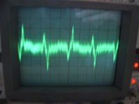
The noise I measure/ see on the scope is obviously rectifier noise. There is allso a trace of 50 Hz on the third channel closest to the Toroid, but rectifier noise seems to be the predominant problem.
Measuring at the PSU connection terminals, there is a relatively clean 100 Hz sawtooth ripple, but this doesn't have the "spiky" character of the 100Hz noise I measure on the outputs.
To me, it looks like rectifier switching spikes is being radiated from the secondary windings of the Toroids, and picked up by the X-over card circuitry.
If I connect the ground clip and the tip of the scope-probe and simply move this about in the vicinity of the Toriod, the spikes show up on the scope quite clearly, easily several mV in amplitude.
Assuming that I've now taken care of any ground-loops and got the PSU right in terms of a basic proven design etc, this looks like the only area left to deal with.
I have found that I can acheive a good deal with magnetic shielding in the form of mu-metal foil and steel plates, up to the point where I need to get close to the speakers to hear noise.
The only other avenue of pursuit would be to reduce the offending rectifier noise, which is after all the source.
Now, I used expensive super-de-luxe fast & soft recovery diodes to build the rectifiers, but obviously this was by no means a final solution.
Is there any other effective way of reducing the switching spikes and/ or preventing them from rushing back through the Toroid secondaries and cause emission of noise??
I've read about "snubber capacitors", could that be an effective countermeasure??
Unfortunately, this had no effect I could identify on the scope, the noise on the outputs is stil there.
The good thing, is that I've elliminated another possible problem source.
The noise I measure/ see on the scope is obviously rectifier noise. There is allso a trace of 50 Hz on the third channel closest to the Toroid, but rectifier noise seems to be the predominant problem.
Measuring at the PSU connection terminals, there is a relatively clean 100 Hz sawtooth ripple, but this doesn't have the "spiky" character of the 100Hz noise I measure on the outputs.
To me, it looks like rectifier switching spikes is being radiated from the secondary windings of the Toroids, and picked up by the X-over card circuitry.
If I connect the ground clip and the tip of the scope-probe and simply move this about in the vicinity of the Toriod, the spikes show up on the scope quite clearly, easily several mV in amplitude.
Assuming that I've now taken care of any ground-loops and got the PSU right in terms of a basic proven design etc, this looks like the only area left to deal with.
I have found that I can acheive a good deal with magnetic shielding in the form of mu-metal foil and steel plates, up to the point where I need to get close to the speakers to hear noise.
The only other avenue of pursuit would be to reduce the offending rectifier noise, which is after all the source.
Now, I used expensive super-de-luxe fast & soft recovery diodes to build the rectifiers, but obviously this was by no means a final solution.
Is there any other effective way of reducing the switching spikes and/ or preventing them from rushing back through the Toroid secondaries and cause emission of noise??
I've read about "snubber capacitors", could that be an effective countermeasure??
Last edited:
rectifier recovery time current spikes are us time scale
if you see anything at sweep speeds that show 100 Hz then that’s not your biggest problem
the reservoir caps draw huge charging current spikes for a few ms around the peaks of the AC input even with "perfect" diodes
you can only smooth the charging current spikes out with bulky power chokes - often requiring similar size as the PS xfmr
if you can't afford the space for the inductors to efficiently smooth the current then you can only try to reduce the loop area the current surges flow through to reduce the field they radiate
JCX to the rescue again!
Thanks for clarifying the nature of the spikes I see, seems I jumped to some rather inaccurate conclusions there..😱
Not the first time and it certainly won't be the last! (I'm afraid..)
The rectifier diodes I'm using 60EPF04 pdf, 60EPF04 description, 60EPF04 datasheets, 60EPF04 view ::: ALLDATASHEET ::: are quoted as having a recovery time of 70uS at 1A.
From what you say, this won't be visible on the scope when with 2ms time/ div, and in that case, the only explanation is then that this is those charging current spikes you describe.
But why does this show up as sharp and relatively short spikes, and not more like a smooth "sawtooth" as the ripple I measure on the PSU output terminals?
Not doubting your explanation here, just curious...😕
Huge chokes and associated additional filters are an impossibility from a space point of view, I need to work with what I have.
I guess that elliminates snubbers and any additional filtering as remedies for getting to the noise...
Regarding the source of the radiation, I doubt that this actually comes from the loop formed by the secondaries connection wires (very short), diode-to capacitor connection.
When moving the shunted scope probe in this vicinity, it doesn't pick up much, but move it close to the Toroid.. things happen.
To me this suggests that the charging spikes, when surging through the secondaries, as they have to do, causes corresponding electromagnetic spikes to be radiated by the entire winding. (just as I, errouneously, assumed the switching spikes did in the last post)
Seems magnetic shielding is the only tool available left for me then...
Hi Elbert, what is the relative size of the 100Hz ripple on the PS output and the spikes you are seeing on the amp output? The sawtoooth waveform you are seeing on the PSU output may be too big in comparison for the spikes to show up. What do the spikes look like if you change your scop to say 100uS per division.. if they look like impulse responses then they are probably your rectifier charging pulses (going on what I've seen in sims not measured with a scope).
Tony.
Tony.
If I remember correctly, I think the sawtooth ripple on the PSU output terminals was arround 40-50 mV.
The spikes on the amp output is aaround 10-15 mV and exactly that; spikes, not a clean waveform.
Got the amp hooked up to the stereo now not the scope (for a change...) but the spikes do look like you describe; Impulse responses.. 🙂
Glad I bought that second sheet of mu-metal, looks like that is my only weapon left in this battle against the hum!
Say, perhaps that could work with your playmate amp as well??
You can get it of e-bay: http://cgi.ebay.com/ULTRAPERM-80-Mu...078?pt=LH_DefaultDomain_0&hash=item19c1a8a7be
If your problem is EMI, which it seems like, this can be surprisingly effective. And If it doesn't work, you can probably use it for some other interresting project, like a phono pre-amp or something! 🙂
Last edited:
If you simulate the current flow through of a rectifier you will find that it isn't as you'd traditionally expect it to be as current is only drawn from the peaks of the sine wave, rather then from the whole thing. At least according to this...
Elliott Sound Products - Linear Power Supply Design
And I do remember simulating this myself at one point too.
I think you need solid proof that it's radiation from the xformer that's causing the issue before you go spending money. Remove the transformer from the case strap some extra cable onto the secondaries and move it a good 30 CM away from the main unit.
I have experienced transformer noise myself and it's not pretty, but you have to be sure that that's the cause. Usually you leave room in a chassis to experiment with transformer positions, because they can at times be a pain. Unfortunately in your case, this isn't possible, the only real solution might be to give the transformer it's own separate box.
5th,
Thanks for a very instructive and interresting article on PSU design! 🙂
Unfortunately, I have wired the transformer rather "solid" to the rest of the PSU, so removing it at this stage is a bit of hassle.
But I think the readings I get on the scope when moving the "looped" scope-probe in the vicinity of the Toroid, and the big effect of placing a strip of mu-metal between the toroid and the x-over card is very strong evidence, especially after I elliminated many other possible culprits through modifications of the PSU and wiring etc..
I'd hate to remove the PSU from the amp-chassis alltogether, as this would sort of break my goal of getting two compact amplifier modules, one for each channel.
Having said that, the amplifiers seem to be very little affected, the problem is (obviously to me) hum induction in to the x-over card.
So in stead of moving the toroid out of the chassii, it might therefore be an alternative to move the x-over out of the amplifier chassii and in to a pre-amp (which I intend to build annyway), and connect to the amp chassii via a multi-cable.
So far, adding shielding in the form of two steel plates and a narrower mu-metal strip reduces the noise to where it is only audible very close to the speaker, so an additional layer of mu-metal might reduce the noise to a level where it will for all practical purpose be insignificant. This might not get the noise down to the theoretical lower limit possible with the amplifiers, but if practically inaudible, this will be more of academic interrest. (?)
If shielding is reducing the hum down to levels like that, then I think it probably is all induced. If this is because of the active xover card only, then moving it into another case would be a good move, especially if another case is on the cards for a preamp.
It also makes sense why the hum wasn't an issue through the tweeter channel, the high pass was helping to blocking it. I am of course assuming this is as measured from the scope, obviously it isn't an issue on the tweeter channel as the tweeter's natural response is many many decibels attenuated by 50/100hz, so is less noticeable.
It also makes sense why the hum wasn't an issue through the tweeter channel, the high pass was helping to blocking it. I am of course assuming this is as measured from the scope, obviously it isn't an issue on the tweeter channel as the tweeter's natural response is many many decibels attenuated by 50/100hz, so is less noticeable.
Back again!
After being away on trael and then chopping up some more steel plates, I'ts time to post some findings and results again.
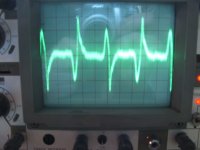
I removed any magnetic shielding plates, and hooked the scope to the midrange output of the amp.
That gave me about 12mV p-p of rectifier noise.
I then removed the steel bolt holding the transformer in place and that reduced the noise to only 8mV p-p, a good improvement, so those nylon bolts I bought was a good investment!
Attached you will find the scope traces, 2mV/div. something wrong here.. can't upload images..
After being away on trael and then chopping up some more steel plates, I'ts time to post some findings and results again.
I removed any magnetic shielding plates, and hooked the scope to the midrange output of the amp.
That gave me about 12mV p-p of rectifier noise.
I then removed the steel bolt holding the transformer in place and that reduced the noise to only 8mV p-p, a good improvement, so those nylon bolts I bought was a good investment!
Attached you will find the scope traces, 2mV/div. something wrong here.. can't upload images..
What does the power supply into the mid-range show?
What does the power supply at the PSU caps show?
What does the power supply at the DC side of the rectifier show?
What does the power supply at the PSU caps show?
What does the power supply at the DC side of the rectifier show?
PSU had about 50 mV ripple at idle current, which I believe is pretty good.
But again, this is a problem of rectifier and Toroid noise being induced in the x-over card..
This will be evident as I present some interresting measurements here..
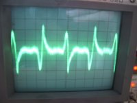
First trace, shows the effect of inserting only one steel plate between X-over and Toroid. Note that the scope is now set to 1mv/ Div.
This looks rather good.
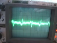
Now, insert all 4 plates, one covered with permalloy foil and the noise goes up again! Interresting, quite contrary to my expectations..
Ok, looks like 1 single steel plate is optimum for the midrange channel, but what about the other channels? Best to check...
But again, this is a problem of rectifier and Toroid noise being induced in the x-over card..
This will be evident as I present some interresting measurements here..
First trace, shows the effect of inserting only one steel plate between X-over and Toroid. Note that the scope is now set to 1mv/ Div.
This looks rather good.
Now, insert all 4 plates, one covered with permalloy foil and the noise goes up again! Interresting, quite contrary to my expectations..
Ok, looks like 1 single steel plate is optimum for the midrange channel, but what about the other channels? Best to check...
Attachments
- Status
- Not open for further replies.
- Home
- Amplifiers
- Power Supplies
- A Grounding challenge , please help..