It happened while I was reading the Thread "Personal Tube Amp DIY Project", that forumer Stalker dropped a link to a somewhat psichedelic page, containing a strange schematic, drawed in a strange style hard to interpret..
http://www.lacieg2s.ca/public/w3terra/ols/flingpoo-visit.htm
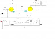
Cause I'm curious I provided to re-draw it in a more understandable way, and quickly found two thing that didn't like me.
The direct- to- the- wall socket transformerless connection and the two 680uF caps connected positive to ground. Once fixed these inconvenients, I continued not to understand how the heck the preamp tube was working with nothing under the cathodes. I asked about this to a fellow from another forum, UNIXMAN, (and Diy Audio member as well). He told me about the ancient grid leak bias, so I figured that at the end, the thing could actually work .
At this point, what I liked was the crude simplicity of the single secondary to carry out the whole duty, and the minimum parts count. Non the less, it was possible to build it absolutely on the cheap.
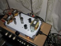
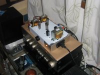
So here it is at work the thingy with the strange name :
"Cancerous Tumortronix "Fleabreeze" Kawabunga 2300 **"
http://www.lacieg2s.ca/public/w3terra/ols/flingpoo-visit.htm
Cause I'm curious I provided to re-draw it in a more understandable way, and quickly found two thing that didn't like me.
The direct- to- the- wall socket transformerless connection and the two 680uF caps connected positive to ground. Once fixed these inconvenients, I continued not to understand how the heck the preamp tube was working with nothing under the cathodes. I asked about this to a fellow from another forum, UNIXMAN, (and Diy Audio member as well). He told me about the ancient grid leak bias, so I figured that at the end, the thing could actually work .
At this point, what I liked was the crude simplicity of the single secondary to carry out the whole duty, and the minimum parts count. Non the less, it was possible to build it absolutely on the cheap.
So here it is at work the thingy with the strange name :
"Cancerous Tumortronix "Fleabreeze" Kawabunga 2300 **"
Attachments
Last edited:
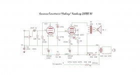
Because I didn't have the 5751 tube, and dont want to buy one , I'm using a 12BX7 in place. Nex days I'll try other tubes that I have at home: 12BH7, 12AU7 and 12AT7.
The thingy is driven a pair of Wharfedale Diamond II, and sounds pretty good. But I suppose that this kind of power is more usable with high sensitivity fullranges.
The thingy is driven a pair of Wharfedale Diamond II, and sounds pretty good. But I suppose that this kind of power is more usable with high sensitivity fullranges.
Cool.
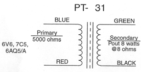
Those are quite beefy OPTs for a 50C5. I usually see a 12AX7 in front of those. With modern CD player less gain would likely be better. I expect the output is on the order of 2W.
dave
Those are quite beefy OPTs for a 50C5. I usually see a 12AX7 in front of those. With modern CD player less gain would likely be better. I expect the output is on the order of 2W.
dave
The power TX is running a bit hot (Triad N68X) But I read somewhere in the forum that, according to Willy Studer, that's Ok 🙂
These are the OPT's, from AES
Some pics:http://picasaweb.google.es/FuchoCrespi/FleabreezeAmplifier?authkey=Gv1sRgCNrXtP_KpqCQYw#
These are the OPT's, from AES
Some pics:http://picasaweb.google.es/FuchoCrespi/FleabreezeAmplifier?authkey=Gv1sRgCNrXtP_KpqCQYw#
Attachments
Last edited:
Mosquito:
Hi there...couldn't make sense of your redraw as I think you muffed it..no power going to your 5751 so I did another redraw in the more "conventional" configuration.....& now it makes sense for me at least.
I am concerned about using half wave rectification...It really strains you power TX...& the ripple must be rather high.
But your saying it sounds good..No ripple to speak of on your B+?
Perhaps you could go with some full wave rectification...perhaps it would bring down the heating effect on your mains TX.
__________________________________________________________Rick....
Attachments
..no power going to your 5751
B+ delivered via R5. A lot of vintage schema are drawn this way. Always makes me look twice.
I prefer the conventuon of the B+ coming from above as shown by Richard.
Richard, you have the OPT ratio incorrectly labeled. The OPT used is 5K to 8R, Mosquito is using a 4R speaker to bring that down to 2.5k plate load that the 50C5 wants to see.
dave
Planet 10 your sight is long range. Effectively the 12BZ7 was inadequate with this component sizes. I just switch to an GE 12AU7WA and the volume gets twice as louder. Later I'll try the 12BH7, just for fun. Now those Wharfedale are rocking!
Richard, I'm a noob with tubes, and since this dude, designer J.Rosen puts a half wave rectifier(followed by massive filtering), I suppose he does so for some reason other than, cost of a 1N4007. So I'd like to try it to the letter, before I think on mods..There is just little hum present, but is hardly noticeble while playing music, and more likely to blame the plain "rats nest" layout style, than the rectifier method. (IMO)
Richard, I'm a noob with tubes, and since this dude, designer J.Rosen puts a half wave rectifier(followed by massive filtering), I suppose he does so for some reason other than, cost of a 1N4007. So I'd like to try it to the letter, before I think on mods..There is just little hum present, but is hardly noticeble while playing music, and more likely to blame the plain "rats nest" layout style, than the rectifier method. (IMO)
Last edited:
Just to be faithfully in the Cheapo spirit, the volume control is a double-gang 100K linear pot , modified as per :ESP - A Better Volume Control
What difference could be using the original 250K size?
What difference could be using the original 250K size?
Well after trying the 12BH7, the volume drops, but the sound was more softer than the 12AU7, I finaly put on the 12AT7 (NOS Westinghouse) That's the tube! Plenty of volume and bass is awesome! I'll stick on it.
Yes I know this trial and error isn't the right method, but I'm not able to carry PSpice simulations. Someone that can, sure will found why the 12AT7 runs better in this circuit.
Now I just will listen to the music. Later will check the actual voltages in the points of interest and sign it on the schematic.
I don't get it. Where is the bias for the first stage? As drawn, can't tell is crossed lines are a junction or just crossed.
Hi, look at the schematic by Richard Ellis, maybe you can found it easier to interpret. It's grid leak biased trough the 10 Mohm R4.
... married girl don't You wanna smoke a little Marijuana ... Ah.. The Slackers.. What a sound is coming out !
... married girl don't You wanna smoke a little Marijuana ... Ah.. The Slackers.. What a sound is coming out !
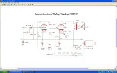
I sure as heck can't see how the grid would ever be made negative with respect to the cathode. Anyone know of an external link that discusses this further? Nothing in Jones.


Mosquito,
To get the most from each of these tubes, you really do need to optimize the plate & cathode resistors,
dave
To get the most from each of these tubes, you really do need to optimize the plate & cathode resistors,
dave
Mosquito,
That img link points to something on your c-drive. You'll need to use the manage attachment button and upload the image to the forum before we can see it.
dave
I sure as heck can't see how the grid would ever be made negative with respect to the cathode. Anyone know of an external link that discusses this further? Nothing in Jones.
I'm pretty sure Morgan touched on it. Only useful if you are using very small amounts of bias. Attach the cathode to ground and use a really big grid leak (on the order of 10M). For the expense of 1 more resistor you can get better control.
dave
I sure as heck can't see how the grid would ever be made negative with respect to the cathode. Anyone know of an external link that discusses this further? Nothing in Jones.
Google for "grid leak bias".
Mosquito,
To get the most from each of these tubes, you really do need to optimize the plate & cathode resistors,
dave
I'll check by first the effective B+ under load, and then tweak these.
Not too much to do with the preamp tube, unless I switch to a more common grounded K configuration
Any suggestion?
- Status
- Not open for further replies.
- Home
- Amplifiers
- Tubes / Valves
- A flea thingy that sounds good