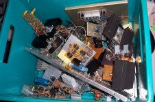
I have begun sorting my "hardware archives": there was no room left in the dedicated cupboard, and this meant it was time to part with my less valuable prototypes (or the most useless ones, depending on the point of view).
Basically, each time I have some silly idea, I build a quick and dirty prototype, made of junk material I happen to have handy.
Sometimes it works satisfactorily, and I dump it into the "archives", and sometimes it doesn't, and it follows the same way, pending further investigations.
The result is identical however: they all end up undisturbed, layer after layer.
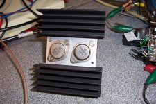
The first pic shows some the "good" (functional or partly functional) prototypes I managed to sort so far.
I have completely forgotten about most of these circuit (although I also have a corresponding heap of paper documentation too), but I picked up a nice little gem I remember of: it is essentially an opamp (TLO82) driving a pair of darlington transistors in the crudest way, without bias or anything.
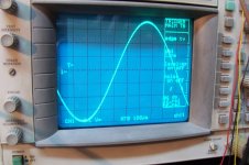
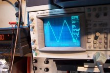
Yet, it manages an acceptable quality, as the oscillogram shows (7.5V@1KHz pp into 5Ω).
What trick does it use?
It uses HF bias, just like magnetic recordings: the other half of the opamp is configured as a ~150KHz oscillator, and it superimposes a few volts to the PA.
An inductor and a series LC circuit block most of the HF in the output, but this is sufficient to overcome the ~2.4V of the unbiased darlingtons, eliminating practically all of the horrific Xover distortion.
A small residue at the dithering frequency is still visible.
It is a kind of linear class D amplifier......
Basically, each time I have some silly idea, I build a quick and dirty prototype, made of junk material I happen to have handy.
Sometimes it works satisfactorily, and I dump it into the "archives", and sometimes it doesn't, and it follows the same way, pending further investigations.
The result is identical however: they all end up undisturbed, layer after layer.
The first pic shows some the "good" (functional or partly functional) prototypes I managed to sort so far.
I have completely forgotten about most of these circuit (although I also have a corresponding heap of paper documentation too), but I picked up a nice little gem I remember of: it is essentially an opamp (TLO82) driving a pair of darlington transistors in the crudest way, without bias or anything.
Yet, it manages an acceptable quality, as the oscillogram shows (7.5V@1KHz pp into 5Ω).
What trick does it use?
It uses HF bias, just like magnetic recordings: the other half of the opamp is configured as a ~150KHz oscillator, and it superimposes a few volts to the PA.
An inductor and a series LC circuit block most of the HF in the output, but this is sufficient to overcome the ~2.4V of the unbiased darlingtons, eliminating practically all of the horrific Xover distortion.
A small residue at the dithering frequency is still visible.
It is a kind of linear class D amplifier......
Attachments

I guess you could also build a bias spreader to set the NPN Darlington's Vbase = +1.9VBE and to set the PNP Darlington's Vbase = -1.9VBE, then AC couple the bias oscillator(s) waveform into these two bases. You would still have zero bias current in the output stage.
You could arrange for the AC waveforms at the two bases to be perfectly in-phase, or perfectly out-of-phase (180 degree shift), or perhaps somewhere in between (90 degrees?).
You could arrange for the AC waveforms at the two bases to be perfectly in-phase, or perfectly out-of-phase (180 degree shift), or perhaps somewhere in between (90 degrees?).
I believe Self has some comments on the HF bias in his new edition. One of many clever tricks that do seem to work, but never caught on as other issues arise.
Yes, if the initial dead zone is reduced it will improve matters undoubtedly, but the main attraction of such a scheme is its simplicity and straightforwardness combined with acceptable performances: straight connection between bases, between emitters, and direct drive by the opamp output.I guess you could also build a bias spreader to set the NPN Darlington's Vbase = +1.9VBE and to set the PNP Darlington's Vbase = -1.9VBE, then AC couple the bias oscillator(s) waveform into these two bases. You would still have zero bias current in the output stage.
If spreaders are added, they will require bias too and the initial simplicity will be mostly gone
I think the in-phase option is the best, because it maximizes the level of the carrier available for the intermodulation to take place.You could arrange for the AC waveforms at the two bases to be perfectly in-phase, or perfectly out-of-phase (180 degree shift), or perhaps somewhere in between (90 degrees?).
If that condition is not met, some of the signal will be lost in the fight between the two signals, and ultimately there is also a risk of cross-conduction.
Refinements are certainly possible, but it will always be at the expense of simplicity.
As it is, the circuit has the advantages of a class D in low power mode, whilst retaining the linearity and bandwidth of a linear amplifier for large signals. Not that bad for such a simple and problem-free circuit
I am not sure I understood how it works. Would you please put up a schematic, even a sketch on paper ?
Is it like the sound signal (LF) is AM modulating a RF signal? But even so I do not see how it overcomes the Xover zone.
Is it like the sound signal (LF) is AM modulating a RF signal? But even so I do not see how it overcomes the Xover zone.
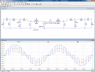
I managed to find an approximate schematic, but it isn't very helpful for comprehension, I'll try to explain it in a simplified way, first in the time domain because it is more intuitive.
In this example, the Xover distortion is simulated using just diodes.
The first pic shows the 1KHz input signal (green) and the distorted output at point a (red).
The second pic shows the result of linearly adding a 2Vpp, 10KHz squarewave: point b, blue.
The choice of squarewave and 10KHz is for clarity of the graphics; in reality, it would be a poor choice.
You notice that if you mentally average the squarewave, you find the original sine, even in the Xover region, because the square amplitude is larger than the Vbe of the diodes.
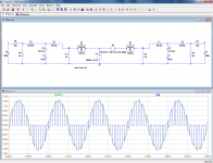
The 10KHz can also be removed by a filter: third pic.
For a fair comparison, the uncorrected output is also filtered in the same way.
On the blue trace, you notice that the step in the 0V region has been completely polished off. The 1KHz amplitude is also somewhat larger.
The sinewave doesn't look clean: that is because of the filtering, and the 1 to 10 ratio of signal to carrier frequency which is much too low and generates additional intermod products.
With a proper choice of carrier frequency, as in the real circuit, the waveform is much cleaner.
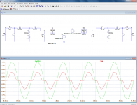
The fourth pic shows the whole thing in more details, with a larger input amplitude and a different scale.
In the frequency domain things are not as intuitive, but it also provides useful informations.
The non-linear junctions can be seen as a modulator: with an input spectrum containing Fs and Fc, it will create Fc+Fs and Fc-Fs. But things won't stop there: it will also generate harmonics of both the carrier and the signal (they are the ones that create the Xover distortion), and it will go even further: all of the above will mix and combine, and generate tens of supplementary intermod products and so on.
Most of these products will be located around or above Fc, (and they will be filtered out) but the low frequency ones are interesting: they will reinforce the Fs fundamental, and cancel its harmonics.
Some higher order products will be located between Fs and Fc, just like in class D, which is why it is important to chose a high enough frequency.
We have seen the voltage aspect so far, but the current side is as important: the current at Fc must be sufficient to drive the output load, which is why the post filter must not present a too high impedance at the carrier frequency.
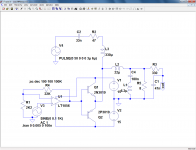
The fifth pic is an approximate schematic of the circuit presented; L2 is not too large, and a series resonant circuit is added at the output, to maximize the current at the carrier frequency and accessorily help remove unwanted residues.
It is one possible implementation, but there are many alternatives: the carrier frequency can also be injected separately, see last pic for example
In this example, the Xover distortion is simulated using just diodes.
The first pic shows the 1KHz input signal (green) and the distorted output at point a (red).
The second pic shows the result of linearly adding a 2Vpp, 10KHz squarewave: point b, blue.
The choice of squarewave and 10KHz is for clarity of the graphics; in reality, it would be a poor choice.
You notice that if you mentally average the squarewave, you find the original sine, even in the Xover region, because the square amplitude is larger than the Vbe of the diodes.
The 10KHz can also be removed by a filter: third pic.
For a fair comparison, the uncorrected output is also filtered in the same way.
On the blue trace, you notice that the step in the 0V region has been completely polished off. The 1KHz amplitude is also somewhat larger.
The sinewave doesn't look clean: that is because of the filtering, and the 1 to 10 ratio of signal to carrier frequency which is much too low and generates additional intermod products.
With a proper choice of carrier frequency, as in the real circuit, the waveform is much cleaner.
The fourth pic shows the whole thing in more details, with a larger input amplitude and a different scale.
In the frequency domain things are not as intuitive, but it also provides useful informations.
The non-linear junctions can be seen as a modulator: with an input spectrum containing Fs and Fc, it will create Fc+Fs and Fc-Fs. But things won't stop there: it will also generate harmonics of both the carrier and the signal (they are the ones that create the Xover distortion), and it will go even further: all of the above will mix and combine, and generate tens of supplementary intermod products and so on.
Most of these products will be located around or above Fc, (and they will be filtered out) but the low frequency ones are interesting: they will reinforce the Fs fundamental, and cancel its harmonics.
Some higher order products will be located between Fs and Fc, just like in class D, which is why it is important to chose a high enough frequency.
We have seen the voltage aspect so far, but the current side is as important: the current at Fc must be sufficient to drive the output load, which is why the post filter must not present a too high impedance at the carrier frequency.
The fifth pic is an approximate schematic of the circuit presented; L2 is not too large, and a series resonant circuit is added at the output, to maximize the current at the carrier frequency and accessorily help remove unwanted residues.
It is one possible implementation, but there are many alternatives: the carrier frequency can also be injected separately, see last pic for example
Attachments
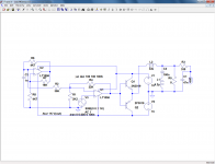


Yes, here are the asc's of the circuits in question:Is schematic #5 (copied below) correct?
Attachments
One or two things I forgot to mention about these circuits: they are not intended as constructible amplifiers, but as objects for study of the concept, ie. to show as much as possible its deficiencies: for example, in W2, the feedback R4 is taken from the output of the opamp, while the sensible thing to do is to take it from the emitters, to include the transistors in the feedback loop.
But doing so would obfuscate most of the transistor's bad behavior, and that's precisely what we want to examine.
Also, the 2P transistors are just bogey types, ideal complementaries of the 2N with just a sex-change operation in the spice definition.
But doing so would obfuscate most of the transistor's bad behavior, and that's precisely what we want to examine.
Also, the 2P transistors are just bogey types, ideal complementaries of the 2N with just a sex-change operation in the spice definition.
This is a nice idea. It may work better with modern transistors that are faster.
However, would it pass FCC? It would need to be in an unrestricted radio band emitting low enough power without harmonics that would interfere with higher bands.
However, would it pass FCC? It would need to be in an unrestricted radio band emitting low enough power without harmonics that would interfere with higher bands.
Filterless class D schemes do pass the FCC.However, would it pass FCC? It would need to be in an unrestricted radio band emitting low enough power without harmonics that would interfere with higher bands.
This one has a filter, and the carrier level is ~20dB lower compared to class D.
To clean up further, one could use a sinewave as carrier. I have used a squarewave, but it is purely for simplicity reasons: the sine would work similarly, if not better.
To clean up further, one could use a sinewave as carrier. I have used a squarewave.
Your circuit in attachment #5 of post#6 uses a bi-exponential sawtooth as a carrier. U2's inverting input terminal (the carrier) swings an exponential waveform from -3.1V to +3.1V, then it reverses and makes another exponential waveform from +3.1V to -3.1V. The timeconstant of the exponentials is R6*C2.
You are right: I confused this one with other experiments.Your circuit in attachment #5 of post#6 uses a bi-exponential sawtooth as a carrier. U2's inverting input terminal (the carrier) swings an exponential waveform from -3.1V to +3.1V, then it reverses and makes another exponential waveform from +3.1V to -3.1V. The timeconstant of the exponentials is R6*C2.
The ~sawtooth is less harsh than a squarewave, but not as clean as a sinewave
Elvee owns the most fascinating cupboard ever.
Such spaces are only for things of merit, all of which have been replaced, some of which shouldn't have been replaced. After only a very few entries, it becomes impossible to remember which is the case, with the only data remaining is that all of them are of merit.
As for my own cupboard, it is much simpler and more sparse; however, I remember that all of it has a favorable tone, passable function, and that the amplifiers have either excellent imaging or excellent dynamic power but not both, the buffer is perfect and unnecessary, and that the radios have either fantastic imaging or fantastic tone but terrible reception except for the one that has fantastic reception and does nothing else well. Oh for pete's sakes! 🙂 One of the amplifiers is probably worth re-visiting--the 2007 LM1875 Turbo style (gain comp) could be changed to the 2013 version by adding 3 parts. So, it seems that my life is a bit less advanced, I should have tried inverting mode and put that buffer to work a lot more often, and somewhat less complicated.
Nevertheless, I have experienced my own slightly fascinating "physical models" cupboard, and am ever so fascinated at even the suggestion to possibly raid Elvee's cupboard, bearing in mind that the only way for electronics to end up there is that they were of special merit, and that means, practically, endearing in some way. That is utterly fascinating.
If I can find some time this WE, I'll try to extract some (master)pieces of crap from my cupboard (crates actually)Elvee owns the most fascinating cupboard ever..
Yes, it is a software tuner by Sony, with all of the complicated matters done wonderfully well and all of the simple matters done horribly wrong. All of the most complex repairs have been completed already, so that only the simplest remain. However, the purchase of a very big antenna has made the Sony redundant. There's about 18 cents worth of parts left to install before the last of its flaws are gone; however, the subminiature parts are slow to work on and, I'm not really in a hurry for it.Dan, does the tuner with good reception and bad tone have a special kind of detector?
A standard feature on ALL new software radios is a regulator at power input, which does seem to cost either some reception or some excessive heat (without any other flaw). The updated practice of cleaner power has made the newer radios both more practical and easier to deploy.
The Sony predates this practice so that its elementary and unstable power amplifiers are also running on dirty power, resulting in the tone of a cat auction in addition to insufficient imaging. That is a problem I can fix, although I think it quite daft for it to have excellence in all categories except for output. Practicalities, Egads!
The mysteriously meritorious items in the cabinet ended up there because, although you liked them enough to preserve them, they were replaced. The replacement was because of something better in fact or because of something new that was supposed to be better and wasn't. It is the latter case it needs exhumed because it is the most fascinating of all.If I can find some time this WE, I'll try to extract some (master)pieces of crap from my cupboard (crates actually)
Also likely is a case of BOTH, that it was replaced for something better in fact, but some or most of your recent projects already contain the needed clues to perfect the cupboard item, resulting in performance that is better or at least more applicably practical than its newer replacement. After all, the bottom line is that you saved it because you liked it. I think that may be extraordinarily meritorious.
And, reverse-murphy's law applies! The cupboard items were probably replaced for something new and improved. There does not exist a louder/brighter warning indicator than that.
P.S.
In an unrelated note, that TracerPhone thing worked perfectly with the guesstimated and ineffective looking clipper values that actually doubled its headroom, and about 6v, which was the maximum. The variable voltage facility did not work at all because it still had to be trimmed to a given voltage, but fortunately a 6v reg was just fine. It was easy to power and produced a low wattage output, with most excellent quality tone AND imaging. Tone and imaging features typically conflict with power output. However, even 2 out of 3 desirable audio features is rarely seen with such perfection. I did not detect either a compression/tonal hot spot nor its mirror a blur. That thing works great with headphones, but also leads to a question if it could be the voltage amp of a larger and lovely sounding power amplifier. With some trimming effort, the thing was exactly transparent. Well, that is rare for a voltage amp. Could there be more such fascinating things in the cupboard, some of which could be boosted to give that blast from the past the needed blast?
Last edited:
In fact, most of the items are experiments and proofs of concept. Some didn't work as expected (see my latest buffer for example, which will probably end there), but I couldn't resolve myself to scrap them, I had the hope that someday, I would have a bright idea and rescue them.The mysteriously meritorious items in the cabinet ended up there because, although you liked them enough to preserve them, they were replaced. The replacement was because of something better in fact or because of something new that was supposed to be better and wasn't. It is the latter case it needs exhumed because it is the most fascinating of all.
Also likely is a case of BOTH, that it was replaced for something better in fact, but some or most of your recent projects already contain the needed clues to perfect the cupboard item, resulting in performance that is better or at least more applicably practical than its newer replacement. After all, the bottom line is that you saved it because you liked it. I think that may be extraordinarily meritorious.
And, reverse-murphy's law applies! The cupboard items were probably replaced for something new and improved. There does not exist a louder/brighter warning indicator than that.
I am a "keeper", and I particularly hate to scrap the result of my own work....
The others have been successful which means I instantly lost interest with them. I have a very short attention span...
In principle, I knew they were available as body parts, usable for complete projects, but in practice it didn't work that way: I have completely forgotten them.
I am glad you found this humble amplifier pleasant. It is just functional but perfectly OK, in the style of amplifiers made in the early seventies.P.S.
In an unrelated note, that TracerPhone thing worked perfectly with the guesstimated and ineffective looking clipper values that actually doubled its headroom, and about 6v, which was the maximum. The variable voltage facility did not work at all because it still had to be trimmed to a given voltage, but fortunately a 6v reg was just fine. It was easy to power and produced a low wattage output, with most excellent quality tone AND imaging. Tone and imaging features typically conflict with power output. However, even 2 out of 3 desirable audio features is rarely seen with such perfection. I did not detect either a compression/tonal hot spot nor its mirror a blur. That thing works great with headphones, but also leads to a question if it could be the voltage amp of a larger and lovely sounding power amplifier. With some trimming effort, the thing was exactly transparent. Well, that is rare for a voltage amp. Could there be more such fascinating things in the cupboard, some of which could be boosted to give that blast from the past the needed blast?
It certainly has some phonic character, because of its low feedback.
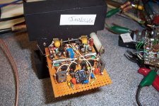
I have dug out some items from my "hardware archives".
The first (the two first pics) is labeled "instable", and that what it is: below +/- 22V, it doesn't amplify at all, and a few volts above that, it breaks into uncontrollable oscillations. Very narrow operating window.
It seems to be intended to be ultrafast, with the MOSFets driven by PP drivers. Basically unusable in that condition.
Next one is more modest: a unity-gain buffer. It may deserve some more attention though: It works spotlessly, and seems to have good performances.
The oscillogram shows a 20KHz triangle on a load of 3 ohm. Not bad.
From what I gather, it seems to be of the error-correcting breed.
I would need to find the schematic. This won't be easy: I'll have to browse through thousands of sheets of notes. Might be simpler to reverse-engineer it.
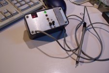
I cannot resist displaying another find: this one is a completed apparatus, and it still works, sort of.
Let us make it into a quiz. Could you guess its purpose?
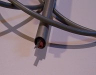
It has three LEDs, a power ON/OFF switch, a function switch, a touch-control pad, a buzzer, a two digit 7-segment display and a mysterious sensor/probe.
OK, it is not directly related to audio, but it can also be useful in this context (and many others).
Attachments
Last edited:
😀 Most of my "cupboard" circuits get some of their part's recycled into better and/or different "cupboard" projects.🙂
Mystery device:
With battery power and a touch pad, it probably compares a human, assumed as 0v to *something else* and discovers the differential (and also the location)? A tracer? A bug sweeper?
Instable device:
Flip the op amp to inverting? That's my only guess. Starting with an op-amp and then following it with a complexity doesn't make sense visually. Generally speaking, op-amps are for shortcuts and that one sure didn't. Is it a nesting arrangement or howland?
Buffer:
It looks like it wants to buffer--the symmetry is pretty. Kudos.
Last edited:
- Status
- Not open for further replies.
- Home
- Amplifiers
- Solid State
- A dive into the past