Some years back I was at a friends shop and listening room and we were working with some Altec 15" coaxes that were missing their horns. Someone there said he could 3D print news horns. I said "Great, can we do a soccer ball pattern?" He said to send him the drawing, which I did, but never heard back. I don't know if they got printed or or even modeled.
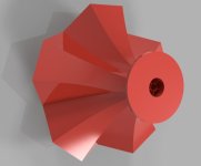
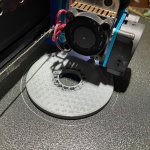
Fast forward about 12 years and I now have a 3D printer and can bash and thrash my way thru drawing in Fusion 360. So I jumped in. What would they look like? I have some renderings to show, and am printing some tests at the moment. The geometry was much more complex to draw than I anticipated, and my limited skills didn't help. But here they are.
The reason for the truncated icosahedron (football) shape is that the pentagon and hexagon fit together so well on the surface of a sphere, no gaps. This shape also makes it easy to do a "sort of" round multi-cell horn. I have drawn some other shapes - all hexagons, circle in the middle with arcs around the edge and some others, but the soccer ball shape looks the coolest. 🙂
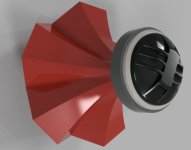
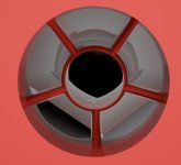
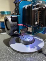
Below you can see what the throat looks like. This is for a 1" driver and you can see how the pentagon and hexagons have been brought into rounded shapes to fit the round opening of the driver exit. No wasted space. You can also see that the fins are brought to a point where they face the driver exit. Finders crossed that works.

Tomorrow I should have some photos of the test prints. Right now the flange and the start of the throat are test printing.
Attachments

Last edited:

Hi @Pano.,
about two years ago I made a similar pattern as an insert for Altec 288 throat, reasoning that breaking the throat into a plurality of "channels" a perimeter of each being sized to be smaller than the wavelength at 20,000 Hz, would extend the high frequency by avoiding cancellation, but I could not measure any improvement.

Now I wonder if I should continue with the idea mating it into a horn similar to yours.
Kindest regards,
M
about two years ago I made a similar pattern as an insert for Altec 288 throat, reasoning that breaking the throat into a plurality of "channels" a perimeter of each being sized to be smaller than the wavelength at 20,000 Hz, would extend the high frequency by avoiding cancellation, but I could not measure any improvement.
Now I wonder if I should continue with the idea mating it into a horn similar to yours.
Kindest regards,
M
Last edited:
This is a very interesting project. Too bad it made no difference, that is surprising. Tell me more, was insert contained entirely inside the 288, or did it extend into the horn?about two years ago I made a similar pattern as an insert for Altec 288 throat
Let us know how it turns out! I've been thinking about something similar as a way to extend the throats of tweeter horns to make time alignment easier.Hi @Pano.,
about two years ago I made a similar pattern as an insert for Altec 288 throat, reasoning that breaking the throat into a plurality of "channels" a perimeter of each being sized to be smaller than the wavelength at 20,000 Hz, would extend the high frequency by avoiding cancellation, but I could not measure any improvement.
View attachment 1435720
Now I wonder if I should continue with the idea mating it into a horn similar to yours.
Kindest regards,
M
Pano, your horn idea looks very interesting and beautiful.
The insert from mefistofeliz - I am surprised there was no difference , even if the walls were paper thin, with the triangles invading the throat; that would change the compression ratio - maybe the reflections from this are advantageous? Could the smaller throat area work better? I would not know.
Went against all the little I know.
A simple annular ring arrangement is said to improve the Celestion Axi-Periodic.
Hi @Pano, @Fuling, @rickmcinnis,
Furthermore, the measurements made no sense to me as in my understanding, the "hash" at the higher frequencies is caused by the diaphragm breakup, so the insert should have no effect.
I was trying to find the measurement data, but at about that time my laptop died, and I could not find a backup. But now, with @Pano attempt, I am interested to revisit the issue, perhaps by remeasuring the insert itself and mated to a horn, or even integrate the insert with a multi-cell horn as per @Pano's brilliant idea, as I like multi-cell horns despite them appearing to be currently out of vogue.
@Pano,
do you think that you could give me some pointers how to extend the channels into a horn?
Kindest regards,
M
P.S. If anyone is interested, I would be happy to share the 3D drawing.
M
Perhaps the measurement that I did was not appropriate for evaluating the effect. I first measured the driver by itself, i.e., without any horn, then I inserted the insert (clumsy English - sorry), into the throat and measured again. I have a vague recollection that there was less "hash" at the higher frequencies, but since my goal was to extend the high frequencies, I did not peruse this any further.This is a very interesting project. Too bad it made no difference, that is surprising. Tell me more, was insert contained entirely inside the 288, or did it extend into the horn?
Furthermore, the measurements made no sense to me as in my understanding, the "hash" at the higher frequencies is caused by the diaphragm breakup, so the insert should have no effect.
I was trying to find the measurement data, but at about that time my laptop died, and I could not find a backup. But now, with @Pano attempt, I am interested to revisit the issue, perhaps by remeasuring the insert itself and mated to a horn, or even integrate the insert with a multi-cell horn as per @Pano's brilliant idea, as I like multi-cell horns despite them appearing to be currently out of vogue.
@Pano,
do you think that you could give me some pointers how to extend the channels into a horn?
Kindest regards,
M
P.S. If anyone is interested, I would be happy to share the 3D drawing.
M
That needs some thought.do you think that you could give me some pointers how to extend the channels into a horn?
 I have given a lot of thought to extending the flange into the driver exit hole, but doing that simply as a way to get the exit profile I want from a driver with a wide flare (most modern compression drivers). Perhaps your idea could be combined with mine, extending the multi cells right down into the driver. That might be difficult with 1" exit drivers, but not too bad with 2" exits.
Hi @Pano,
Essentially, my problem is how to expand the outer cells/channels without impinging on the middle one - without any gaps - which you seem to have solved.
Kindest regards,
M
Perhaps I did not explain myself correctly, the quoted portion of your reply is exactly the idea.Perhaps your idea could be combined with mine, extending the multi cells right down into the driver. That might be difficult with 1" exit drivers, but not too bad with 2" exits.
Essentially, my problem is how to expand the outer cells/channels without impinging on the middle one - without any gaps - which you seem to have solved.
Kindest regards,
M
Hi @Pano.,
about two years ago I made a similar pattern as an insert for Altec 288 throat, reasoning that breaking the throat into a plurality of "channels" a perimeter of each being sized to be smaller than the wavelength at 20,000 Hz, would extend the high frequency by avoiding cancellation, but I could not measure any improvement.
View attachment 1435720
Now I wonder if I should continue with the idea mating it into a horn similar to yours.
Kindest regards,
M
I'm no expert in phase plugs, but I've made quite a few: https://www.diyaudio.com/community/threads/diy-compression-drivers.317125/
As I understand it:
When the diameter of the wavefront is smaller than the duct in which it's traveling through, a wave can't form because there simply isn't enough room for it to form.
For instance, 16khz is 0.844 inches long (21.4mm). If you subdivide a 25.4mm throat, like you did, there might be a small improvement in the overall smoothness at VERY high frequencies (13.5khz and higher.)
If you had a peak or a notch, doing something like what you did, I would expect that it would (possibly) smooth things out. If the high frequency response is already smooth, I wouldn't expect this phase plug to INCREASE the output at high frequency, because the output at high frequency is determined by mass and force. IE, you could increase high frequency output by lowering the mass of the diaphragm, increasing the force of the motor, or both. Again, all of this assumes that there are no peaks or cancellations caused by pathlength differences. If there ARE, then an improved phase plug is exactly what you need.
I will make a couple draws to see what I can do.how to expand the outer cells/channels without impinging on the middle one - without any gaps
pentagon and hexagon fit together so well on the surface of a sphere
Geodesic dome… you could call it a Fuller Milti-cell
dave
Hi @Pano,
Kindest regards,
M
Thank you. Thee is no rush though, as I have at least another month of work before I can get back to any non-work project.I will make a couple draws to see what I can do.
Kindest regards,
M
Hi @Patrick Bateman,
So do I understand your quote as arguing that my perceived smoothing of the peaks an valleys were due to curing the path difference?
Kindest regards,
M
Just like you, I do not pretend to be any expert on this. However, from reading some smart people, it is my understanding that when the wavelength exceeds the dimension of the duct, a path difference and, therefore cancellation occurs. So, the "hash", i.e., the peaks and valleys.at higher frequencies are due to both the cancellation, and reinforcement, as well as the result of the diaphragm breakup..If you had a peak or a notch, doing something like what you did, I would expect that it would (possibly) smooth things out. If the high frequency response is already smooth, I wouldn't expect this phase plug to INCREASE the output at high frequency, because the output at high frequency is determined by mass and force. IE, you could increase high frequency output by lowering the mass of the diaphragm, increasing the force of the motor, or both. Again, all of this assumes that there are no peaks or cancellations caused by pathlength differences. If there ARE, then an improved phase plug is exactly what you need.
So do I understand your quote as arguing that my perceived smoothing of the peaks an valleys were due to curing the path difference?
Kindest regards,
M
For whatever its relevance -- this tissue roll center waveguide performed miraculously...
My foot-of-bed diystudio. Up-firing vintage Alnico 8" over stylish trashcan. The waveguide (tissue roll center) really flattens out mid-hi response and widens directivity; tonality is just right. Image floats midair beyond speakers/wall. Really no complaints, difficult to turn off music. (1st-gen Huawei P10plus streaming Baidu cloud, my EAC-rip/hdtracks/etc multi-T library. Ancient iPadPro records nicely too. OCC interconnect a must. TPA3221-on-steroids. Close enough to my earlier "retreat" system: highly tweaked musicPC/fb2k, Chord Hugo, Bel Canto, Monitor Audio Studio etc.)...
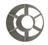
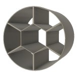
@mefistofelez To make your 288 throat insert with less lost area and blockage, you might try something like this. One idea keeps your hexagonal center, the other goes to rounds. All these cells should be approximate the same area; 1/7th of the total.
Attachments
- Home
- Loudspeakers
- Multi-Way
- A different sort of Multi-Cell horn. 3D printing.