I think when driving Allison from the outside edges rather than between emitters,
you lose all local error corrections of hot output emitter voltage. Making distortion
fixes entirely dependent upon the global loop. Added complexity for little else but
temperature compensated sliding bias...
you lose all local error corrections of hot output emitter voltage. Making distortion
fixes entirely dependent upon the global loop. Added complexity for little else but
temperature compensated sliding bias...
bias current
I'm not sure if you already answered this question, but what was bias current corresponding to the simulation results you gave at the begining of this thread.
Regards
I'm not sure if you already answered this question, but what was bias current corresponding to the simulation results you gave at the begining of this thread.
Regards
thank klewis. I will take more time to study Allison's circuit.This configuration looks quite similar to HEC. Here it's called Allison. There is a bit more on the Allison configuration do a search for "Simulation Allison" and you will find Keantokens original thread.
I believe you asked how to calculate the resistor values for HEC. The one resistor R14 in this circuit between the two Allison transistors Q8/Q10. I set the value of R14 by trial and error based upon the size of heat sink that I have. The smaller the value of R14, the lower the bias of the output transistors. For my set up, my heat sinks can handle a bias of about 500mA at each device. The heat sinks are about 8 inches square with 2 inch fins. For the simulations that I have been working with here, I've been using this 500mA bias or about 24watts as measured in simulation at the output devices.
I'm not sure if you already answered this question, but what was bias current corresponding to the simulation results you gave at the begining of this thread.
Regards
see Post #37 about 590mA
I think when driving Allison from the outside edges rather than between emitters,
you lose all local error corrections of hot output emitter voltage. Making distortion
fixes entirely dependent upon the global loop. Added complexity for little else but
temperature compensated sliding bias...
KenPeter,
I built one example (not a simulation) and it wasn't a happy day or amp. But, I'm always will to try again. Somehow, the distortion fixes from the global loop are pretty good, arguably better than a triple emitter follower.
KenL
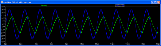
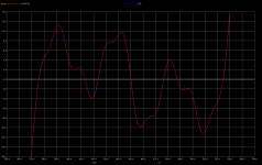
The red trace is the input signal multiplied by the amp gain a 'control reference', and the blue trace is the output signal, at 20KHZ, 100KHZ, 500KHZ
Cheers
Arturo
Arturo,
same set up as yours, though it won't go to 500kHz. images: 20k clip, 100k clip, 500k overview, 500k zoom
regards,
Ken
Attachments
Ahh.. your simulation is not going right. 2n3906 as input can not do that good, it only fast.
Here my simulation with original model. Results only 0.004% THD at 1kHz, while my VAS has 0.0002% THD at 10kHz.
How could you get such linearity with bad VAS linearity huh?.
Do not trust your sim results, they are not going right.😕
Get models from Bob Cordell's web site their hFE curves match and other features match the data sheets much more closely. Most manufacturers models a nasty bad...
Ken
Originally Posted by ontoaba
Ahh.. your simulation is not going right. 2n3906 as input can not do that good, it only fast.
Here my simulation with original model. Results only 0.004% THD at 1kHz, while my VAS has 0.0002% THD at 10kHz.
How could you get such linearity with bad VAS linearity huh?.
Do not trust your sim results, they are not going right.
But what is the purpose to measure the VAS alone?. When loaded with the rest of the power stage(s) it will change (for worst), but it is irrelevant, what matters is the linearity at the output, or I am missing something?
Cheers
Arturo
Ken, I would like to see other characteristics of your amp such ... premises of design you had in mind ... or any other useful information.
Cheers
Arturo
Arturo,
To explain the premise, let me tell you where I've been and where I want to go. I came to this site after reading Jack Walton's article on the LME4702 in audio express. I then found the LME49811 which is a single 4702. I then started looking at double and triple emitter followers to tack on the end of it. I built a few, and maybe like most newbies struggled a bit getting the bias to work amongst other issues. But then it worked and I tried variations with Thermal Trac devices and other things. I found Keantoken's thread on the allison variations and built one biased fully in ClassA. It sounded great but got pretty hot with 32volt rails. Then PaulbySouth was kind enough to show me a ClassA/B variant. I built that as well. In all I built and tested 7 distinct variations and several versions of some of the variations. What I found was, when played, the sound had more air and clarity than the emitter followers.
I'm looking for an amp in the 50watt range, possible scalable to 100watts. My speakers are efficient enough to make good volume levels at 1watt. I'm not a rocker anymore, rather prefer music that involves the nuances of the human voice.
Parallel to the physical tests I was also making simulations. But, I was using the spice tools to represent the VAS portion of the amp. I don't know enough to be sure that the VAS portion was well represented in the simulations. When Bob Cordell made his models and simulation available along with a book to explain there workings I decided to plug the Allison in and compare to the triple emitter follower. Maybe these side by side comparisons would explain the differences that I was hearing. Additionally I could look at modifications to both the VAS and output that would take advantage of the unique characteristics of the Allison.
What I believe that I am hearing and what several of you have suggested is the low H2/H9 distortion at low power across the audible spectrum is audible(or in comparison to a triple, in-audible). So, this is a feature to enhance without hurting the high power end. The second characteristic I would like to work on is reducing the noise at these low volume levels, then test to see if this doesn't also improve the sonic qualities.
I will also note, as I did before that I was surprised to see the distortion of a triple rises rather dramatically as the frequency rises. This distortion could vary well be effecting the air of the sound.
In this pursuit I have implemented TMC in simulation, but not tested it yet. I will also build a discrete VAS to replace the 49811 as I have found some improvement to the VAS on the noise front that are built-in to the 49811.
Ken
BAD and GOOD
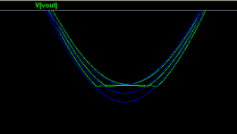
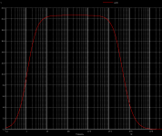
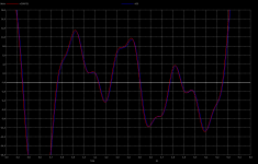
I agree most of your opinions. Now you will understand the 'HI FI Bandwidth' with the following example. Here I show 2 sets of pix's to show the behaviour of 2 amps a BAD and a GOOD. This example isn't far from reality, found in some low end amps, both amps are feed with some 'music material', the red trace represents the shape that the amp should reproduce accurately and the red trace is the reproduced shape of actual output.
pix 1 is the BW of the BAD amp
pix2 is the reproduction of the BAD amp at 1KHZ fundamental, seems to be fairly accurate. It is capable to reproduce 10+ harmonics of the input shape.
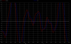
pix3 is the BAD amp at 10KHZ fundamental (still at hearing range). The amp is not capable to reproduce accurately. Indeed will have a big impact on trebles, it will reproduce a pasted sound (without air) without resolution.
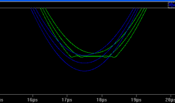
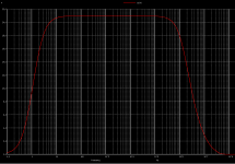
pix 4. is the BW of the GOOD amp.
pix 5. Shows a very accurate shape at output. It can reproduce a flat band of 100KHZ+ with low distortion all over the BW. Therefore most of the harmonic content (=shape) of the music will be reproduced accurately. That makes the trebles ie: horns, reeds, cymbals, piano, percussion all with rich harmonic content to sound with very high definition, it should have a good sound. Moreover many people 'tune' Cdom to get the final amp sound, what they are doing is changing the BW and the slew.
Cheers
Arturo
Arturo,
To explain the premise, let me tell you where I've been and where I want to go. I came to this site after reading Jack Walton's article on the LME4702 in audio express. I then found the LME49811 which is a single 4702. I then started looking at double and triple emitter followers to tack on the end of it. I built a few, and maybe like most newbies struggled a bit getting the bias to work amongst other issues. But then it worked and I tried variations with Thermal Trac devices and other things. I found Keantoken's thread on the allison variations and built one biased fully in ClassA. It sounded great but got pretty hot with 32volt rails. Then PaulbySouth was kind enough to show me a ClassA/B variant. I built that as well. In all I built and tested 7 distinct variations and several versions of some of the variations. What I found was, when played, the sound had more air and clarity than the emitter followers.
I'm looking for an amp in the 50watt range, possible scalable to 100watts. My speakers are efficient enough to make good volume levels at 1watt. I'm not a rocker anymore, rather prefer music that involves the nuances of the human voice.
Parallel to the physical tests I was also making simulations. But, I was using the spice tools to represent the VAS portion of the amp. I don't know enough to be sure that the VAS portion was well represented in the simulations. When Bob Cordell made his models and simulation available along with a book to explain there workings I decided to plug the Allison in and compare to the triple emitter follower. Maybe these side by side comparisons would explain the differences that I was hearing. Additionally I could look at modifications to both the VAS and output that would take advantage of the unique characteristics of the Allison.
What I believe that I am hearing and what several of you have suggested is the low H2/H9 distortion at low power across the audible spectrum is audible(or in comparison to a triple, in-audible). So, this is a feature to enhance without hurting the high power end. The second characteristic I would like to work on is reducing the noise at these low volume levels, then test to see if this doesn't also improve the sonic qualities.
I will also note, as I did before that I was surprised to see the distortion of a triple rises rather dramatically as the frequency rises. This distortion could vary well be effecting the air of the sound.
In this pursuit I have implemented TMC in simulation, but not tested it yet. I will also build a discrete VAS to replace the 49811 as I have found some improvement to the VAS on the noise front that are built-in to the 49811.
Ken
I agree most of your opinions. Now you will understand the 'HI FI Bandwidth' with the following example. Here I show 2 sets of pix's to show the behaviour of 2 amps a BAD and a GOOD. This example isn't far from reality, found in some low end amps, both amps are feed with some 'music material', the red trace represents the shape that the amp should reproduce accurately and the red trace is the reproduced shape of actual output.
pix 1 is the BW of the BAD amp
pix2 is the reproduction of the BAD amp at 1KHZ fundamental, seems to be fairly accurate. It is capable to reproduce 10+ harmonics of the input shape.
pix3 is the BAD amp at 10KHZ fundamental (still at hearing range). The amp is not capable to reproduce accurately. Indeed will have a big impact on trebles, it will reproduce a pasted sound (without air) without resolution.
pix 4. is the BW of the GOOD amp.
pix 5. Shows a very accurate shape at output. It can reproduce a flat band of 100KHZ+ with low distortion all over the BW. Therefore most of the harmonic content (=shape) of the music will be reproduced accurately. That makes the trebles ie: horns, reeds, cymbals, piano, percussion all with rich harmonic content to sound with very high definition, it should have a good sound. Moreover many people 'tune' Cdom to get the final amp sound, what they are doing is changing the BW and the slew.
Cheers
Arturo
Attachments
post86.
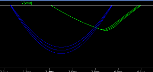
500kHz output looks like it is slew limiting.
If you reduce input/output voltages you should get a much better sinewave at the output.
500kHz output looks like it is slew limiting.
If you reduce input/output voltages you should get a much better sinewave at the output.
As we approach the rail, bias on the drain goes away.
Miller capacitance approaches symmetry with gate to source capacitance.
We have 100R charging gate (and an ever increasing miller) toward the rail.
Yet 320R must discharge all coulombs of stored miller going away from rail.
No sim today is going to show you how the miller caps change with bias.
Problems with large signals can happen at lower frequency than you might
expect.
Last edited:
I agree most of your opinions. Now you will understand the 'HI FI Bandwidth' with the following example. Here I show 2 sets of pix's to show the behaviour of 2 amps a BAD and a GOOD. This example isn't far from reality, found in some low end amps, both amps are feed with some 'music material', the red trace represents the shape that the amp should reproduce accurately and the red trace is the reproduced shape of actual output.
pix 1 is the BW of the BAD amp
pix2 is the reproduction of the BAD amp at 1KHZ fundamental, seems to be fairly accurate. It is capable to reproduce 10+ harmonics of the input shape.
pix3 is the BAD amp at 10KHZ fundamental (still at hearing range). The amp is not capable to reproduce accurately. Indeed will have a big impact on trebles, it will reproduce a pasted sound (without air) without resolution.
pix 4. is the BW of the GOOD amp.
pix 5. Shows a very accurate shape at output. It can reproduce a flat band of 100KHZ+ with low distortion all over the BW. Therefore most of the harmonic content (=shape) of the music will be reproduced accurately. That makes the trebles ie: horns, reeds, cymbals, piano, percussion all with rich harmonic content to sound with very high definition, it should have a good sound. Moreover many people 'tune' Cdom to get the final amp sound, what they are doing is changing the BW and the slew.
Cheers
Arturo
With your test, his amp will marked as BAD. I have tried to help him and told him to use my VAS, but he wouldn't understand.
As we approach the rail, bias on the drain goes away.
Miller capacitance approaches symmetry with gate to source capacitance.
We have 100R charging gate (and an ever increasing miller) toward the rail.
Yet 320R must discharge all coulombs of stored miller going away from rail.
No sim today is going to show you how the miller caps change with bias.
Problems with large signals can happen at lower frequency than you might
expect.
Sorry, that reply was supposed to be for Improving the Goldmund thread...
Mods can remove from this thread if they wish, I've already copied over.
Last edited:
Are you sure? Did you verify the BW and the slew of Ken's amp?Ontoaba ...
With your test, his amp will marked as BAD. I have tried to help him and told him to use my VAS, but he wouldn't understand.
I didn't yet simulated Ken's amp nor yours (showed in your last thread) because I am very busy and takes me a lot of time typing the circuit in text mode, as I use Unix and don't have a GUI frontend as LTSpice.
My philosophy is:
BANDWIDTH more than ultra low THD's at 1KHZ which means nothing, I am satisfied with a design if it has >=100V/us of slew a flat up to 200KHZ TF with a THD of <=0.01% over the whole BW, with rapid decreasing of the harmonic profile (low IMD), symmetric clipping, low noise, high damping factor > 4000, and STABILITY with the nastiest loads (the GOOD amp meets this requirements in excess).
This is a very interesting answer to Carlos by Bob in the Bob Cordell's book thread that clarifies some of statements above.
http://www.diyaudio.com/forums/soli...lls-power-amplifier-book-154.html#post2489910
Cheers
Arturo
Bandwidth, symmetrical slew, graceful clipping, THD at low and medium levels:
All of great importance. Forced low THD at highest output levels maybe not.
Nothing like when an absolute current or voltage linearity hits a brick wall...
Trying too hard for an impossibly low THD makes other problems unsolvable.
All of great importance. Forced low THD at highest output levels maybe not.
Nothing like when an absolute current or voltage linearity hits a brick wall...
Trying too hard for an impossibly low THD makes other problems unsolvable.
Last edited:
No offense, but I ever using such VAS in my real life, from memory distortion philosophy (I am new with it) the noise will appeared from multi tone test (3tone or more). And I am indicating his simulator results are much different than mine.Are you sure? Did you verify the BW and the slew of Ken's amp?
I didn't yet simulated Ken's amp nor yours (showed in your last thread) because I am very busy and takes me a lot of time typing the circuit in text mode, as I use Unix and don't have a GUI frontend as LTSpice.
I ever use ewb512 with wine, it is working.
I am now collecting and studying as many as I could from greatest amplifiers ever like Yamaha B4/M4 and some Luxman's that used non lateral mosfets, nor tubes. All of them cascoding their transistors.
My philosophy, its different, may be similar with Carlos, it is "Listening". Since distortion figure and slewrate not proofing its truth from listening.
I remember he interested in DF knobs.
Ontoaba:
My philosophy, its different, may be similar with Carlos, it is "Listening". Since distortion figure and slewrate not proofing its truth from listening.
I can bet that most people at listening prefers some distortion. I am a sax player aficionado and I really hate BAD trebles, not to say I have a privileged audition but I can feel when something is missing ...
Cheers
Arturo
My philosophy, its different, may be similar with Carlos, it is "Listening". Since distortion figure and slewrate not proofing its truth from listening.
I remember he interested in DF knobs.
BS, for the simple fact that your ears are not a calibrated instrument and all the processing takes place between you ears which is highly subjective and very susceptible to outside influences. Blind ABX comparisons prove that time after time.
Having said that, can we please keep subjective (or opinion) based experiences out of this discussion please and focus on verifyable simulation or measurement results.
Cheers,
Sander.
I can bet that most people at listening prefers some distortion. I am a sax player aficionado and I really hate BAD trebles, not to say I have a privileged audition but I can feel when something is missing ...
Cheers
Arturo
That is why I am placing FB stage switch at my sample. Pre final feedback has around 0.1%THD and beautiful treble, post final feedback has much lower distortion but hard treble. This thing happened in both high speed amplifier and proper speed amplifier.
I found that output stages draw really visible different current wafeform from that differences but the output voltage waveform almost the same.
ok🙂Having said that, can we please keep subjective (or opinion) based experiences out of this discussion please and focus on verifyable simulation or measurement results.
Last edited:
- Status
- Not open for further replies.
- Home
- Amplifiers
- Solid State
- A different CAS typology with very low THD