Victor board mounting on the front panel and wiring photos - part 2
More photos...
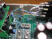
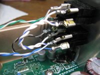
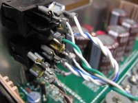
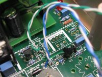
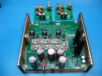
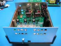
* The next 4 show the wiring to the rear panel switches. Again, the obvious thing, be vary careful to mind polarity in all of this! 🙂 I believe I have the positive terminal marked on each board section.
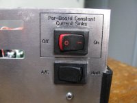
So I have a green/white pair going from the CCS row feed to the middle contacts of that top rocker on the rear panel, which is the CCS cut-off switch. Then a short twisted pair jumper goes from the near side of the that switch to the middle contacts of the DPDT below, the AC/Battery select switch. So whichever you select - AC or Battery - gets sent up to that CCS on/off switch and on to the CCS row. I put that top switch there just as a handy way to turn off all 4 CCS (and hence all 4 victor boards) at once, without having to turn off each front panel switch.
Then the blue white pair from the battery section output goes to the near side DPDT contacts, while a brown/white pair comes up from the voltage regulator outputs to the far side DPDT contacts.
I'm just using CAT5 pairs here. 😀 But I built up one of these for another forum member last year and I used some since multi-strand silicon covered wire. I love that stuff, it is extremely flexible.
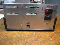
* The next two are just the back panel switches with the labelling, as a reminder of which goes where.
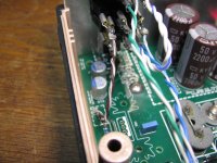
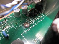
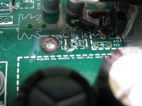
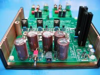
* The next two show one of those truss head screws doing its thing, the voltage regulator mounted on the rear panel with the insulators, and also the two jumpers there near the screw. Don't forget about those two, they pass the power from the votlage doubler on to the voltage regulator section.
Those jumpers are there so the batteries could be fed to the voltage regulator section instead, if someone wanted.
I don't have C11 installed because intially I had the voltage regulator over in the heat sink position, with a heat sink for table top use while
I was waiting for my rear panel to arrive, ao I populated C11 instead. C11 and C10 are in parallel. I just didn't have the motivation to remove C11 and move it to C10 after de-soldering the vreg / heatsink and moving the vreg to the rear panel position. So your board is correct in having C10 populated. That really is where it should go if you are using the rear panel position for the vreg.
* Finally a close up of the battery and CCS power feeds.
Remember that clicking on the arrows in the lower left corner of these will zoom the up, same with the photos in part 1.
More photos...
* The next 4 show the wiring to the rear panel switches. Again, the obvious thing, be vary careful to mind polarity in all of this! 🙂 I believe I have the positive terminal marked on each board section.
So I have a green/white pair going from the CCS row feed to the middle contacts of that top rocker on the rear panel, which is the CCS cut-off switch. Then a short twisted pair jumper goes from the near side of the that switch to the middle contacts of the DPDT below, the AC/Battery select switch. So whichever you select - AC or Battery - gets sent up to that CCS on/off switch and on to the CCS row. I put that top switch there just as a handy way to turn off all 4 CCS (and hence all 4 victor boards) at once, without having to turn off each front panel switch.
Then the blue white pair from the battery section output goes to the near side DPDT contacts, while a brown/white pair comes up from the voltage regulator outputs to the far side DPDT contacts.
I'm just using CAT5 pairs here. 😀 But I built up one of these for another forum member last year and I used some since multi-strand silicon covered wire. I love that stuff, it is extremely flexible.
* The next two are just the back panel switches with the labelling, as a reminder of which goes where.
* The next two show one of those truss head screws doing its thing, the voltage regulator mounted on the rear panel with the insulators, and also the two jumpers there near the screw. Don't forget about those two, they pass the power from the votlage doubler on to the voltage regulator section.
Those jumpers are there so the batteries could be fed to the voltage regulator section instead, if someone wanted.
I don't have C11 installed because intially I had the voltage regulator over in the heat sink position, with a heat sink for table top use while
I was waiting for my rear panel to arrive, ao I populated C11 instead. C11 and C10 are in parallel. I just didn't have the motivation to remove C11 and move it to C10 after de-soldering the vreg / heatsink and moving the vreg to the rear panel position. So your board is correct in having C10 populated. That really is where it should go if you are using the rear panel position for the vreg.
* Finally a close up of the battery and CCS power feeds.
Remember that clicking on the arrows in the lower left corner of these will zoom the up, same with the photos in part 1.
Attachments
-
 IMG_4261.JPG317.9 KB · Views: 500
 -
 IMG_4262.JPG256.4 KB · Views: 487
 -
 IMG_4263.JPG240.6 KB · Views: 478
 -
 IMG_4264.JPG276.7 KB · Views: 463
 -
 IMG_4265.JPG328.3 KB · Views: 469
 -
 IMG_4266.JPG234.5 KB · Views: 227
 -
 IMG_4267.JPG283.2 KB · Views: 215
 -
 IMG_4268.JPG243 KB · Views: 183
 -
 IMG_4269.JPG314.8 KB · Views: 199
Last edited:
Just a bump. Picking up a board from agdr (thanks!) and starting this build sometime soon. Very tidy and well documented project.
BK
BK
New V3.2 boards, LiPoly "9V", and new optional DP3T rotary rear panel CAD
New V3.2 boards
I've just updated the first post in this thread to say that I've received a bunch of new V3.2 boards. No functionality or part changes at all vs. 3.1, just a couple of minor things. A change list is out on the project Google Drive link in the first post.
Can use multiple "9V" battery types
Just a reminder that if you use batteries with the board you can use primary "9V" (throw away batteries) OR NiMH rechargeable "9V" ("8.4V nominal) OR lithium polymer rechargeable "9V" (7.4V nominal). That is why the board has the 7 battery clips, to adjust the number of batteries for the type and use shorting battery snaps on the unused positions. The board does not recharge so rechargeables have to be charged off-line in the battery manufacturer's charger. And no mixing and matching of course, use all one type of battery at a time. 🙂
The lithium polymer 9V are my new go-to batteries in the 9V PP3 form factor if at all possible. In another thread I've measured their internal resistance at just 0.5 ohms, with a 720mAhr capacity. Like these (the ones I measured):
2 Bank 9 Volt Battery Charger with 2 Batteries: BatteryMart.com
battery datasheet:
http://www.batterymart.com/pdfs/rli-9720.pdf (opens PDF)
Amazon sells a couple of LiPoly "9V" brands too. So for lithium polymer you would use all 7 battery positions. The low battery indicator light comes on at 45Vdc total. 45V/7 = 6.43Vdc per battery minimum, which is 3.2Vdc per cell, about as low as you would want to take them to prevent any damage, as per this nice chart over on Adafruit:
https://learn.adafruit.com/assets/979
The board does not have a battery cut-off circuit, just the front panel red "battery low" warning light. You have to manually switch off and recharge the batteries at that point. The boards's constant current sinks pull 25mA through the Victor oscillators. 2 Victor oscillators would be 50mA, so 720mAhr/50mA = 14.4 hours between recharges for LiPoly. Not bad. 🙂
And of course the board has the AC section too, batteries are optional, which brings us to...
New optional rear panel FPE CAD with a DP3T rotary switch
A second, optional, rear panel Front Panel Express CAD design will be posted this coming week too. The existing rear panel CAD design uses a DPDT rocker switch to select power input for the row of per-Victor-board constant current sinks between AC or batteries. The new optional rear panel CAD design will use a 3 position rotary switch instead to also allow selection of the front panel binding posts as an input voltage source, from an external lab supply. Again a reminder why the large rocker switches and this particular DP3T rotary (included in the BOM now as an option), the relatively high voltage DC-breaking requirement. Hard to find small switches rated over 20Vdc breaking. Both Mouser and Digikey stock this particular C&K DP3T rotary switch.
A big thanks to bk856er for the suggestion here of including the binding posts as optional inputs! Up until now folks would have had to leave off either AC or batteries to including binding post voltage input. No more! Now you can have all three.
Last edited:
luvdunhill, are your battery tabs oriented correctly??
Good catch! Part of them are, in fact, in backwards (the photos on post 116). I completely missed that at the time. I can easily get those out with the vacuum desolderer if wick won't do the job. I'll send him a PM. Could be he has been running on AC all this time and never noticed.
On the PC board there is a double circle around one hole on each battery snap. That is meant to be the female snap end. In those photos the 3 near the power supply electros are in correctly, but the 3 near the constant current sinks and the one on the end are reversed.
Last edited:
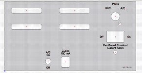
New, optional, rear panel update
Here is an update on the new rear panel design with the DP3T rotary switch, preliminary picture below. So far so good. The lower rocker switch now becomes the master cut-off for the per-board constant current sinks (was the upper switch). The rotary switch for battery-binding posts-AC is now on the top. I did a bunch of calculations today and the body of the rotary switch behind the panel will fit in the space just fine, clearing both the Hammond case lip on the top & right and the rocker switch edge on the bottom by several mm.
But.. there are angles involved, lol. 🙂 I'm going to have FPE fabricate one of these so I can test it before I post it on out the Google drive link. As luck would have it I don't have a knob here that fits the 0.25" D shaft. I've ordered some in from Digikey. I **think** the keyway on the switch is at 30 degrees from the bottom, where I have it here, best I can figure out from the datasheet mech diagram. But that really needs to be tested, and that is assuming the line on the knob-being-shipped is where I think it is relative to the D shaft flat.
So long story short it will be a few weeks before I have the new rear panel design posted. But in the meantime the existing design using 2 rockers is still there at the project Google Drive link. I posted an update to that today which makes the text and engraving a little bolder, went from a 0.2mm engraving tool to 0.4mm. I have tested that on a past panel, I just hadn't posted it yet.
bk856er - thanks again for the suggestion of the 3 way switch to include the binding posts as a power source!
I'm going to be building another one of these boards up for myself! 🙂 I'm getting 4 additional boards from Victor at some new frequencies. I'll build the case up with the rotary switch this time. I have a brand new un-shielded Hammond case that has been sitting here a long time. I'm going to use that and test noise vs. the existing box which I built up in one of the shielded Hammond cases. Just curious!
Attachments
Last edited:
Looking good, agdr!
I finished assembling the board today - just need to clean it, and of course do all the switch wiring and panel fabrication.
I liked that rotary switch so much that I'm going to use a 2-position version for the CCS cutoff and probably put both rotary switches on the front panel.
Your knob clocking looks correct for the D shaft, at least for the 45KN018-GRX knob I'm planning to use - just checked it.
BK
bk856er - thanks for the confirm on the keyway positioning!
Sounds good about the rotary switches on the front panel. If you are not using all 4 Victor board positions might as well! Please post a photo when you get it all done. 🙂
Sounds good about the rotary switches on the front panel. If you are not using all 4 Victor board positions might as well! Please post a photo when you get it all done. 🙂
One interesting thing that did pop up is what appears to be IMD when both the 10KHZ and 11KHz signals are being applied, if I'm looking at that right. In the plots below with both the 10KHZ and 11KHZ signals fed in via the left and right channels I'm seeing 1Khz (difference frequency), 2KHz, 3KHz, etc. Happens with either batteries or AC. There is the chance is could somehow be a result the common ground connection between the two Victor boards. I'm still thinking about a way to isolate whether this is a (dual) Victor ocillator issue or an issue of IMD inside the QA400. Maybe unbolt one oscillator from the front panel and power it with separate batteries. Lol, I'm out of my depth here. Hopefully someone who knows a lot more about this stuff than me can comment.
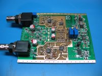
I have been avoiding this thread because I don't need more projects I can't finish. In any case here http://www.diyaudio.com/forums/equi...er-ak5397-ak5394a-ak4490-111.html#post5074313 is the IM performance of two Victor boards running from seperate supplies into two different ADC's. I used separate supplies for each to prevent any ground currents getting shared. otherwise the differential currents will pass through the PCB's and may get into something and cause issues. While I really like the nice box having already built this it was too late. The big round thing is a Daven 600 Ohm decade attenuator (from my junk box). The housing is a cast Hammond box I had and the drill pattern on the front is best described as "free-hand". At least it works. The appetite for 9V batteries is pretty fierce however. Also keep in mind that the frequency drifts with time and changes as the board warms up. I was going to use external injection locking to keep the frequency stable but the added distortion was just too great so I abandoned that phase for now.
Attachments
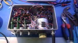
I have been avoiding this thread because I don't need more projects I can't finish.
I completely understand! I have boards and parts here for AIM65's AmpCasq headamp, Sergey888's Crocodile headamp and XRK's class A pocket headamp all just waiting for some time to solder them up. 😀
In any case here http://www.diyaudio.com/forums/equi...er-ak5397-ak5394a-ak4490-111.html#post5074313 is the IM performance of two Victor boards running from separate supplies into two different ADC's.
Hey that is a *very* interesting IMD result! I know that EMU 1212M is pretty highly regarded. Looks like the RTX has it beat.
I like your Victor board box! That does the job quite well. Fully shielded and even an attenuator. I tried some vertical Victor board arrangements when I was selecting a case for the project but I never could find one the right size to also fit in the power supply board. I never did look at their cast boxes, but I did find some near-fits in the half-rack cases. Pricey though, as I recall.
I get similar thermal warm-up drift with the Victor boards. Any more I switch them on and then go do something else for 15 minutes .🙂
Last edited:
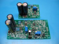
Getting closer. A trio of oscillators coming up!
Looking good! 😀 Good timing, I just soldered some IC2 chips onto a few Victor power supply boards while waiting for a basketball game to start.
Hey looking at your photo it just reminded me that I should be including the bolts and nuts for those constant current sink heat-sinks too. I can't remember doing that. They need to be relatively short (not extend very far past the heat sink fin length) or they will hit the batteries. I can't quite tell the length from the photos but if you want some shorter bolts just send me a PM, bolts and shipping on me. 🙂 Same goes for anyone else who has one of these boards or is building one, if I didn't include those bolts. I use 3mm diameter metric stainless Allen (hex) head bolts and nuts. They use a 2mm metric Allen key. Here in the US Harbor Freight Tools has those for cheap, in a set of metric Allen keys.
Also, in the photos, I'm sure bk856er knows this but for anyone else viewing those nylon standoffs and nylon nuts that ship with it for corner "feet" have to come off when it is time to finally bolt it down to the case with the included four truss head screws. At least I think they need to come off, come to think of it I haven't tried it for height with the standoffs installed vs. the case bottom stud height! Those studs are pretty short though, hence the 1/4" long truss head screws.
Last edited:
What 3rd frequency would be the most useful if I already have the 1k and 10k Victor boards? That third spot is starting to look lonely!
BK
BK
What 3rd frequency would be the most useful if I already have the 1k and 10k Victor boards? That third spot is starting to look lonely!
BK
Trust me, it will look even lonelier as time goes on! 😀 I've regretted not putting a 4th Victor board in my existing case. In the second case I'm building up I'm putting in all 4 boards. Most of the cost with each panel is one time setup for the drilling and engraving, the way Front Panel Express prices things. Adding a few more holes for another Victor board only adds a dollar or two to the cost.
In my existing I have 1KHz, 10KHz, and 11KHz. Those last two are useful for two-tone IMD measurements. As for mixing the two tones, Victor says it is OK to simply connect the two oscillator outputs with an RCA Y cable, since the oscillators have 600 ohm output resistors. An alternate way is to make an op-amp inverting summing circuit:
Summing Amplifier is an Op-amp Voltage Adder
For my second box I'm having Victor build up 260Hz, 7KHz, 19KHz, and 20KHz boards for me. More two-tone IMD stuff, the 260Hz + 7KHz and the 19KHz + 20KHz. The odd-looking 260Hz number was picked just to avoid power line harmonics.
So maybe consider an 11KHz board! If anyone else out there has some thoughts an a 3rd frequency, please do post.
Last edited:
At this performance level you should just use passive mixing. The opamp mixer will limit the distortion floor. Bob cordell had a 3 tone set for IM with some benefits. I have a box built around his concept that works pretty well. There is a good reason to do this in band limited (read digital audio) systems since harmonics don't exist for higher tones but IM products do. CordellAudio.com - A Fully In-Band Multitone Test for Transient Intermodulation Distortion
At this performance level you should just use passive mixing. The opamp mixer will limit the distortion floor.
Makes sense! Thanks.
At this performance level you should just use passive mixing. The opamp mixer will limit the distortion floor. Bob cordell had a 3 tone set for IM with some benefits. I have a box built around his concept that works pretty well. There is a good reason to do this in band limited (read digital audio) systems since harmonics don't exist for higher tones but IM products do. CordellAudio.com - A Fully In-Band Multitone Test for Transient Intermodulation Distortion
Good info - thanks. I'll have to do the math and see if my "10k" can stand in for the triple tone set.
BK
With Victor's help you may be able to retune the oscillator to 10.05 KHz (all of 50 Hz). Or maybe just wait. However my oscillators tend to drift lower so that may not work.Then a 9 KHz and a 20 KHz oscillator. Then a good low pass filter around 2KHz and a decent FFT should get a lot of detail. The older box I acquired from Chuck Hansen uses straightforward filters and has a residual of around .0001% with pretty simple oscillators.
IM testing has not been as interesting I think because it doesn't generate lots of complicated graphs.
Its important to understand that the distortions are all symptoms of underlying nonlinearity. They do not exist on their own. And the non-linearity that generates harmonics also generated IM products. The real virtue of a test like Cordell's is getting good insight in bandlimited (CD) systems. By definition there are zero harmonics on any signal above 11.050 KHz on a CD.
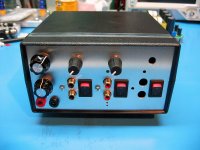
Nearly done. Made some tweaks to agdr's panel layout to move the controls to the front and implement simple banana plug inputs. After a bit of hand drilling and filing and everything fits nicely!
Will probably put some small vent holes above/below the heatsink and see if that works out. If not, I'll move the regulator to the rear panel alternate location.
BK
Will probably put some small vent holes above/below the heatsink and see if that works out. If not, I'll move the regulator to the rear panel alternate location.
BK
Attachments
- Status
- Not open for further replies.
- Home
- Design & Build
- Equipment & Tools
- A case and power supply for Victor's low THD oscillators