Rear panel CAD file now posted, plus build tips
I finallly have the rear panel CAD file for this project done, attached below and also out at the Google Drive link in the first post in this thread.
Front Panel Express made a mistake on the first run of the panel (scratches on it), but they have been good enough to re-run it at their expense and allow me to fix a couple of screw-ups I made at the same time.
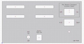
The power jack hole and the mounting hole for the voltage regulator bolt are just exactly spot-on, as the photos show. 😀 However, here is a build tip for both the power jack and the stacked LED on the front panel. There is a small amout of "wiggle room" in the PCB holes on both, around 0.25mm or so in either direction. I used the datasheet recommended holes sizes, which always tend to run just a hair large.
When soldering those parts please be sure to have them lined up as closely as possible to match the silk screeen part outline. The best way is just solder one lead first, then flip the board over and check positioning. If needed re-heat that one lead as many times as need to get the part placement perfect, then solder the remaining leads.
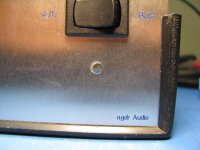
On this one the LED was slightly off to one side, covering up the part silk screen ouline on that side. So I solder-sucked it out and re-did it per the above. Compare the front panel LED photo now to the one I posted weeks ago above. Perfectly centered in the holes now.
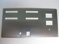
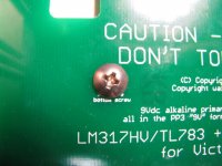
* photo 3675 shows the rear panel as shipped from FPE.
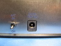
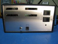
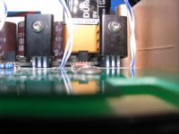
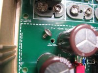
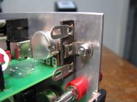
* 3693, 3694, and 3695 show the fit of the rear panel int the Hammond case. in 3695 that is looking through the panel hole and the hole in the tab of the TO-220 LM317HV on the back of the panel! Lol, it doesn't get much more exact than that. Make sure the LM317HV is all the way down on the board as far as the leads allow when soldering it in. Remember that if the rear panel mounting position is used like this the heat sink position on the board doesn't need to be used. They are wired in parallel.
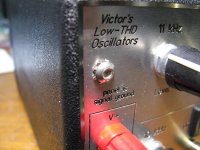
* 3697 is the front panel LEDs now that I solder sucked it and repositioned the part so it fits exactly in the board silk screen outline.
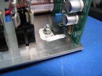
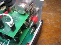
* 3703 and 3704 show the LM317 heat sinked to the rear panel using 3mm stainless steel button-head mounting hardware from Bolt Depot.com. That is a 3mm nylon insert acorn nut on the back. I've gone to those lately in place of a 3mm lockwasher and nut - easier to work with. The standard mica washer, nylong TO-220 hole washer, and heat sink grease are used here to insulate the chip from the rear panel.
I finallly have the rear panel CAD file for this project done, attached below and also out at the Google Drive link in the first post in this thread.
Front Panel Express made a mistake on the first run of the panel (scratches on it), but they have been good enough to re-run it at their expense and allow me to fix a couple of screw-ups I made at the same time.
The power jack hole and the mounting hole for the voltage regulator bolt are just exactly spot-on, as the photos show. 😀 However, here is a build tip for both the power jack and the stacked LED on the front panel. There is a small amout of "wiggle room" in the PCB holes on both, around 0.25mm or so in either direction. I used the datasheet recommended holes sizes, which always tend to run just a hair large.
When soldering those parts please be sure to have them lined up as closely as possible to match the silk screeen part outline. The best way is just solder one lead first, then flip the board over and check positioning. If needed re-heat that one lead as many times as need to get the part placement perfect, then solder the remaining leads.
On this one the LED was slightly off to one side, covering up the part silk screen ouline on that side. So I solder-sucked it out and re-did it per the above. Compare the front panel LED photo now to the one I posted weeks ago above. Perfectly centered in the holes now.
* photo 3675 shows the rear panel as shipped from FPE.
* 3693, 3694, and 3695 show the fit of the rear panel int the Hammond case. in 3695 that is looking through the panel hole and the hole in the tab of the TO-220 LM317HV on the back of the panel! Lol, it doesn't get much more exact than that. Make sure the LM317HV is all the way down on the board as far as the leads allow when soldering it in. Remember that if the rear panel mounting position is used like this the heat sink position on the board doesn't need to be used. They are wired in parallel.
* 3697 is the front panel LEDs now that I solder sucked it and repositioned the part so it fits exactly in the board silk screen outline.
* 3703 and 3704 show the LM317 heat sinked to the rear panel using 3mm stainless steel button-head mounting hardware from Bolt Depot.com. That is a 3mm nylon insert acorn nut on the back. I've gone to those lately in place of a 3mm lockwasher and nut - easier to work with. The standard mica washer, nylong TO-220 hole washer, and heat sink grease are used here to insulate the chip from the rear panel.
Attachments
-
 Victor ps board rear panel.JPG257.3 KB · Views: 529
 -
Sig gen pwr supply 1598EBK rear panel 4.zip883 bytes · Views: 70
-
 IMG_3704.JPG44.5 KB · Views: 167
 -
 IMG_3703.JPG48.3 KB · Views: 173
 -
 IMG_3697.JPG56.4 KB · Views: 143
 -
 IMG_3695.JPG53.4 KB · Views: 509
 -
 IMG_3694.JPG53.5 KB · Views: 520
 -
 IMG_3693.JPG42.5 KB · Views: 510
 -
 IMG_3675.JPG30.2 KB · Views: 520
Last edited:
rear panel build-up photos, part 2
Some more helpful build photos...
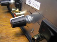
* 3705, 3706 and 3707 show the #6 x 1/4 truss head screws from Bolt Depot for securing the board to the Hammond case. This is the size screw Hammond recommends. The super-flat truss head is just the thing for use under those Victor board (2 of the mounting holes are under the lower oscillator boards). 3707 is a sideway's shot showing the height of the screw head.
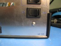
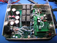
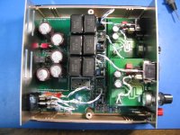
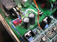
* 3700, 3701 and 3702 show the wiring of the two switches on the rear panel. The bottom switch is a DPDT that selects between the batteries or the output of the LM317HV voltage regulator, fed by the voltage doubler. In this case I've populated 6 of the 9V batteries (around 54Vdc), while the voltage regulator is set for 48Vdc.
The output of the DPDT then feeds to one set of terminals on the top DPST switch, which then goes to feed the row of constant current sinks. This switch is just there to cut off the power to the CCSes entirely to preserve the batteries, if they are being used. There is no particular reason I used insulated fastons for the one wire pair here, I was just trying out the crimper. 🙂 The insulated fastons actually won't fit on the middle contacts of the switches, plus the crimper & dies from Amp/TE were insanely expensive, so the (wire soldered on, not crimped) uninsulated Fastons used here are the best way to go.
The wire I've used here is 22AWG 19-strand twisted-pair silver-coated teflon insulated stuff (from eBay), a notch up from the ethernet cabe strands. I've used the convention throughout to keep the top terminals on all the switches as positive, the wire with the blue stripe.
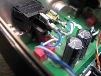
* The remaining 4 photos show the front panel switch and Victor board wiring with the front panel installed. I've used the same convention here, top switch terminal and blue stripe wire is positive. Each board has a short twisted pair that goes from the Victor board connector to the switch Fastons, then from there to one of the constant current sink sections. I haven't pushed the Fastons coming from the CCS sections fully onto the switches here because I needed to remove the panel after the photo. With the Fastons pushed in all the way they have plenty of clearance to those tall electrolytics on the back of Victor's boards. I've left off the 7th battery at the end of the row (it is jumpered with a shorting connector) simply because no additional voltage is needed here. The front panel binding posts and the 2-lug terminal strip are not used in this build since all the power is internal.
If you place an order to Bolt Depot you also might want to order a spare set of the two case screws, flat head Philips 3mm x 10mm bolts, just in case they get lost at some point. 🙂
Some more helpful build photos...
* 3705, 3706 and 3707 show the #6 x 1/4 truss head screws from Bolt Depot for securing the board to the Hammond case. This is the size screw Hammond recommends. The super-flat truss head is just the thing for use under those Victor board (2 of the mounting holes are under the lower oscillator boards). 3707 is a sideway's shot showing the height of the screw head.
* 3700, 3701 and 3702 show the wiring of the two switches on the rear panel. The bottom switch is a DPDT that selects between the batteries or the output of the LM317HV voltage regulator, fed by the voltage doubler. In this case I've populated 6 of the 9V batteries (around 54Vdc), while the voltage regulator is set for 48Vdc.
The output of the DPDT then feeds to one set of terminals on the top DPST switch, which then goes to feed the row of constant current sinks. This switch is just there to cut off the power to the CCSes entirely to preserve the batteries, if they are being used. There is no particular reason I used insulated fastons for the one wire pair here, I was just trying out the crimper. 🙂 The insulated fastons actually won't fit on the middle contacts of the switches, plus the crimper & dies from Amp/TE were insanely expensive, so the (wire soldered on, not crimped) uninsulated Fastons used here are the best way to go.
The wire I've used here is 22AWG 19-strand twisted-pair silver-coated teflon insulated stuff (from eBay), a notch up from the ethernet cabe strands. I've used the convention throughout to keep the top terminals on all the switches as positive, the wire with the blue stripe.
* The remaining 4 photos show the front panel switch and Victor board wiring with the front panel installed. I've used the same convention here, top switch terminal and blue stripe wire is positive. Each board has a short twisted pair that goes from the Victor board connector to the switch Fastons, then from there to one of the constant current sink sections. I haven't pushed the Fastons coming from the CCS sections fully onto the switches here because I needed to remove the panel after the photo. With the Fastons pushed in all the way they have plenty of clearance to those tall electrolytics on the back of Victor's boards. I've left off the 7th battery at the end of the row (it is jumpered with a shorting connector) simply because no additional voltage is needed here. The front panel binding posts and the 2-lug terminal strip are not used in this build since all the power is internal.
If you place an order to Bolt Depot you also might want to order a spare set of the two case screws, flat head Philips 3mm x 10mm bolts, just in case they get lost at some point. 🙂
Attachments
-
 IMG_3712.JPG80.9 KB · Views: 233
 -
 IMG_3711.JPG75 KB · Views: 177
 -
 IMG_3709.JPG57.9 KB · Views: 165
 -
 IMG_3708.JPG77.7 KB · Views: 155
 -
 IMG_3702.JPG78.8 KB · Views: 166
 -
 IMG_3701.JPG83.9 KB · Views: 170
 -
 IMG_3700.JPG73.3 KB · Views: 159
 -
 IMG_3707.JPG49 KB · Views: 165
 -
 IMG_3706.JPG53.2 KB · Views: 154
 -
 IMG_3705.JPG65 KB · Views: 169
Last edited:
Are there any boards available? If not, I would be willing to do a run if others would like one.
Are there any boards available? If not, I would be willing to do a run if others would like one.
I do have boards! 🙂 They are at-cost for anyone on the forum, which is $19.60. They have the gold (ENIG) finish which worked out to be $5 per board of that. The shipping of the boards back to me is also part of that cost.
The board is fairly large, 143 x 148mm and sized to fit in the Hammond 1598 cases. Plastic with aluminum end panels is 1598BK or GY (black or grey) and the internally shielded one is the 1598REBK, all at Mouser (and probably Digikey). Or the board can be used table-top with standoffs in the four corner 3mm holes. Shipping is actual cost from the post office. I'll find out how much. For smaller "first class packages" to the US they charge $2.50, but I'll bet this one is in the $3-$4 range, given the size.
All the project materials are here:
https://drive.google.com/folderview?id=0B67cJELZW-i8blhqM2owVjRlNUk&usp=sharing
Including the BOM, build instructions, schematic, layout, Gerbers (to do a board run), etc. Also .fpd CAD files for Front Panel Express for the front and back panel. One thing to watch out for: Victor changed the height of his ground screw by a few mm with the recent batch of boards (everything else is the same). The CAD files are for the original boards. Anyone sending out panels should determine which Victor board they have (caliper the mid-screw-hole to PCB bottom height if needed) and adjust the ground screw(s) for those board(s) accordingly. Easy to do, the Front Panel Designer CAD program is a free download at FPE. Just read the file in, click on the ground screw hole, and adjust the Y dimension in the left pane. I can help too, let me know if any questions.
Last edited:
Parts ordered! Had to go a capacitance size larger for C8 (820uF) and higher voltage C1 (250V) but both use the same footprint. Everything else was in stock and ready to go.
Parts ordered! Had to go a capacitance size larger for C8 (820uF) and higher voltage C1 (250V) but both use the same footprint. Everything else was in stock and ready to go.
Sounds good! Your substitution for C8 should work just fine. 🙂
Also just a reminder why I wound up using the large rocker switches for power on the panels, the DC breaking rating. Nearly all the small switches were only rated at 28Vdc breaking, as I recall. Higher DC voltages mess with the parts specifications all over the place. 🙂
My package has to travel a total of 100 miles south and UPS says:
"Severe weather conditions have delayed delivery. / We’re working to deliver your package as soon as possible."
Heh, "severe" weather in Texas.
"Severe weather conditions have delayed delivery. / We’re working to deliver your package as soon as possible."
Heh, "severe" weather in Texas.
Lol! I feel your pain. 🙂 I placed a Mouser order at 2PM on Thursday. So another 100 miles down the freeway, should have been here Friday, right? Nope. UPS tracking says Mouser hands the order off to UPS at 11 PM, too late in the day. The package sits the whole holiday weekend in "Brown Wood, TX" and I finally receive it at 3PM on Tuesday. 😡
Two questions right off the bat:
I don't see D1 specified in the BOM (it's located above BT7)
For S1, did you remove one of the legs? There are three positions and two on the PCB.
For the front panel accounting for the difference in PCB thickness, any reason you didn't just make a short slot instead of a hole?
It might be nice to pull the various pictures from the thread and add them to the Drive listing - two of the three picture folders are empty.
I'd probably add another battery connector onto the BOM (and a shot blurb on why you might need to short BT7)
also, what's the verdict with CCS and R18? your latest build shows it jumpered.
I'd probably also add the the BOM isolation pads for the TO-220 parts.
also, what's the verdict with CCS and R18? your latest build shows it jumpered.
I'd probably also add the the BOM isolation pads for the TO-220 parts.
Two questions right off the bat:
Good finds! 🙂
* D1 - sure enough, left that out of the BOM! That is fixed now in the battery section and the BOM reposted on the Google V3.1 link. I tend to worst-case design everything (lol - I did reliability & maintainablity work on F16 jet avionics at one point) and that diode is just polarity protection. For the highly unlikely case of either 6 batteries jumpered and the remaining one touched in reverse, or a majority of batteries in backwards. Hey you never know what folks will do!🙂 For the price of a diode I figured best protect the electronics. A schottky would also work, but I went with a 1N4004 though in case all 7 batteries were in backwards (someone could solder all 7 battery snaps in backwards) - the SB160/1N5819's don't go up that high in reverse voltage.
* S1 - another good find! The unused lead does need to be cut off with wire cutters, near the switch body. I've found that SPDT are more in stock than SPST, and DPDT more than DPST. I've designed a few things this way with the unused leads cut off to save PC board space. I should add this to the build instructions, but for now I've added put a note in the notes column on the revised BOM.
* Good point about PCB thickness, all of the panel holes in the Front Panel Express CAD files are assuming 1.6mm board thickness. I really should put a note about that in the build instructions. If anyone is using a thinner board the switch and power jack holes would have to be adjusted.
* I like your suggestion of moving some of the pictures from the thread into the Google drive! I'll do that.
* Battery shorting clips - added! Another good find. I've added the line item to the battery section in the BOM and a note in the notes column. I put 7 battery snaps in series to cover the worst case of the lowest voltage battery type - lithium rechargesble "9V". For primary cells or NiMH you may not need all 7, depending on how things are wired. The batteries can be wired to directly feed the CCS row, or to go through the on-board voltage regulator. The "standard" way to wire it is with the batteries going to the top rear panel switch just as a master cutoff. Then that switch goes to one side the DPDT below it, with the other side going to the AC voltage doubler section, and the output of the switch in the middle going to the voltage regulators. So you can switch between batteries or AC, and either way it would go through the voltage regulator, then on to the CCS row and out to the Victor boards.
* R18 is in there for maximum flexibility, in case someone wanted to wire up the main voltage regulator section as a single current source instead and use that to feed just one Victor board. 🙂 I made this thing a real Swiss army knife. 😀 I can't envision anyone using that feature, but there it is just in case. So do leave it jumpered for the standard configuration, the per-Victor-board row of depletion mosfet constant current sinks does the job the best.
* Good suggestion on the TO-220 heat sink kit for that rear panel mount votlage regulator. I'll look up the keystrone part number there and add that one later tonight. The heatsinks on each of the four TO-220 depletion mosfets though won't need any isolating washers since they don't touch anything, just some heat sink grease.
For primary cells, other than the additional heat would they actually last a bit longer using all 7? That isn't clear to me.
Panels have been sent off!
Panels have been sent off!
Good news that your panels are in the works! 🙂 I like how the panels turned out. Front Panel Express is pricey but they do excellent work.
Unfortunately the capacities (mAhr) of the batteries in series don't add, only the voltage. So that 7th battery really would wind up as just extra heat dissipation by the voltage regulator.
Unfortunately the capacities (mAhr) of the batteries in series don't add, only the voltage. So that 7th battery really would wind up as just extra heat dissipation by the voltage regulator.
For primary cells, other than the additional heat would they actually last a bit longer using all 7? That isn't clear to me.
Panels have been sent off!
If using a constant current supply you can figure the battery life from the set current vs. the mA/HR and the end of life voltage. An extra battery could get you much further, except and the over discharged batteries are more likely to leak. Feeding a series regulator is pretty similar. A switching regulator can extend the battery life at the cost of significant noise issues.
It would be possible to run the batteries directly to the row of per-Victor-board constant current sinks, but I wouldn't recommend it because of the additional heat dissipation in the CCS. It would be like putting a little heater in front of each Victor board. 🙂 One goal with the design was to try and keep the temperature inside the box as constant as possible, under the assumption that Victor's boards will probably have some degree of thermal drift.
Routing the batteries through the single voltage regulator section first, to drop them down to 45Vdc, puts roughly a constant 35V - 45V= 10V across the DN2540 CCS mosfet for each board. The votlage regulator transfers the bulk of the power dissipation to the case rear panel, on the other end from the Victor boards. Power being a square law thing the CCS'es will dissipate considerably less heat. With all 7 batteries there would be somewhere around 70V - 35V = 35V across each CCS TO-220. In fact, with the much drop, the heat sinks I've specified for the CCS transistors probably wouldn't be enough.
So at the least, if anyone should want to run the batteries directly to the constant current sinks rather than going through the voltage regulator section, probably best to use the battery shorting snaps and limit it to 5 ot 6 batteries, not all 7.
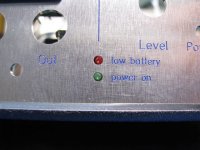
Also remember that low battery LED indicator section! Definitely will want to populate that section if using batteries. It lights the front panel red LED if the total votltage drops below 45Vdc.
Routing the batteries through the single voltage regulator section first, to drop them down to 45Vdc, puts roughly a constant 35V - 45V= 10V across the DN2540 CCS mosfet for each board. The votlage regulator transfers the bulk of the power dissipation to the case rear panel, on the other end from the Victor boards. Power being a square law thing the CCS'es will dissipate considerably less heat. With all 7 batteries there would be somewhere around 70V - 35V = 35V across each CCS TO-220. In fact, with the much drop, the heat sinks I've specified for the CCS transistors probably wouldn't be enough.
So at the least, if anyone should want to run the batteries directly to the constant current sinks rather than going through the voltage regulator section, probably best to use the battery shorting snaps and limit it to 5 ot 6 batteries, not all 7.
Also remember that low battery LED indicator section! Definitely will want to populate that section if using batteries. It lights the front panel red LED if the total votltage drops below 45Vdc.
Last edited:
Great, glad my questions made sense!
My (new) oscillators didn't come with panel nuts, so that might be another part to specify, assuming you used them.
I can find a screw for the regulator and then there is the terminal strip to mount. I guess I will have to order the four M3 screws to affix the board, as a regular machine screw probably won't "cut it"?Does that cover the hardware? Perhaps just add the hardware directly to the BOM as well?
I am going to wait for the panels to wire things up, but here is the progress so far:
What did you end up doing with the front mounted power supply terminals and the terminal strip there? I don't see that configuration populated in any of your pictures!
Also, I don't have panel nuts for 2 of my oscillators. Any idea of the part number that will fit Victor's pots?
Also, I don't have panel nuts for 2 of my oscillators. Any idea of the part number that will fit Victor's pots?
What did you end up doing with the front mounted power supply terminals and the terminal strip there? I don't see that configuration populated in any of your pictures!
Also, I don't have panel nuts for 2 of my oscillators. Any idea of the part number that will fit Victor's pots?
Hey nice build job! I just realized that somehow I didn't have a subscription set up for this thread and missed your post above with the photos.
You even have that tiny IC2 low battery chip soldered in! I would say that one chip is the hardest thing in the entire project due to its size. I have another project going on in the headphone thread, an OPA1688 CMOY, that uses a different newly-released comparator that size, the TPS3701. I gave up an had some small DIP-6 adaptor boards machine assembled for that one. The rest of that project is through-hole, so the one chip would kind of mess up the DIY effort if not DIP. At least this comparator chip is 5 leads instead of 6 (the TPS3701 is 6) which makes that one side a littler harder to solder bridge. 🙂
I see you bought the shielded case too! That is the one I have. $30+ but well worth it.
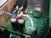
So right off the bat, when you apply power to the AC voltage doubler section those two LEDs will let you know immediately if all is OK with the doubler. I added those on one of the later board runs. When I switch something on that is running at 68Vdc or so I want to know *immediately* if it is working properly! The energy for those LEDs essentially comes for "free" because that is also the power-off safety bleed resistor circuit on each half of the voltage doubler. Those resistors would have to be there anyway as bleeders.
On the panel nuts, is that the nut for the pot on the Victor board that is missing? I have a boatload of 6mm and 7mm nuts and washers, if that is the size he used. I'm on the road right now but when I get back in tonight I'll check the size vs. the Victor board. If they are are right size I'll just pop a few in an envelope. 🙂 How many do you need?
That is interesting, Victor had nuts and washers on the pots on all 3 boards I bought. He must have stopped including them at some point. I agree, I should put those on the front panel BOM.
On that voltage regulator, you need to use a full TO-220 insulator kit (mica washer w/ heat sink grease and the nylon bolt insulator) for mounting that one on the back panel. I have a bunch of those too, I'll put one of those kits in mail too. It has the bolt and nut.
On the M3 screws that mount the board to the bottom half of the case, those need to be special truss (very flat) head M3 screws that a I *should* have included with the board, but sounds like I forgot. Sorry about that! I have those and I'll include those too. In fact I kind of remember now after mailing the board thinking "Did I include the screws?". 🙂 Be sure to screw the board down before inserting your front panel with the Victor boards mounted on it, since the Victor boards sit right over two of the board mounting screws.
I'll take a picture of that mounted terminal strip and post too.
Good progress on it all! The wiring will be the next big challenge. 🙂 Lots of twisted pairs from the CCS sections to the Victor boards, and more twisted pairs from those holes on each board section to the rear panel switches.
Last edited:
Yeah, I don't have any of the Victor panel nuts 🙁
Thanks for the offer, let me see what I am missing - I like the idea of including the truss screws - why Hammond didn't do that we will never know!
The tm other stuff I can get faster from Mouser probably 🙂

Thanks for the offer, let me see what I am missing - I like the idea of including the truss screws - why Hammond didn't do that we will never know!
The tm other stuff I can get faster from Mouser probably 🙂
Victor board mounting on the front panel and wiring photos - part 1
Good deal, you have 3 Victor boards, same as mine!
So here are some photos that should help. I checked the nuts and washers on my Victor boards. They are the same size as 9mm dual pots, M7 with a pitch of 0.75mm. I have a bunch of those. Hopefully Victor hasn't changed pots, on his new boards, or if he has hopefully they have the same threads.
For the pots on my Victor board I had to use one washer in-between the pot and panel in the back, then a washer and nut on the front. That washer in the rear was needed to get the pot to line up perfectly mechanically since Victor has it back just a bit from the board edge.
Then on the ground nuts - at least on his older boards here - It took 3 flat washers in back between the ground nut socket and the panel to close the gap, then on the front I used the screw and external tooth lockwasher. My Victor boards actually came with all that - 3 or 4 flat washers, the ground screw, and the external tooth lockwasher. Let me know if yours is short any of that, I probably have it here.
Also, if you have his new boards, the spacing between that ground screw socket and panel may be different. You may have to mess with adding and removing washers a bit to his board to get it perfectly parallel to the mounting panel. Victor's boards were consistent, though. Once I figured out the right number of spacer washers to get them to sit flat it worked on all 3 boards.
Photos:
* The first two show the flat washer and nut in front of the Victor pot and one washer in back between the pot and rear of the panel.
* The next 3 show mounting of that terminal strip. I don't have mine connected - or the binding posts - because all the power is internal, off the power supply board. I have the posts and terminals there so folks could run power in via the front. They could also be used to run the power supply voltage out the front. You could even do something like build up that 4th constant current sink position and feed the output to the binding posts. That would give you a lab current source at any value you set if you happened to need a CCS for something. 🙂
That looks like I used a M3 stainless button head bolt 6mm or 8mm long for the terminal strip. I'll figure out which and send it. 🙂 The socket on those is M2 (2mm metric). They have those at Harbor Freight tools, a set of 3 foldable metric allen wrenches, English allen wrenches, and torx wrenches for $6 or so.
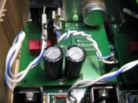
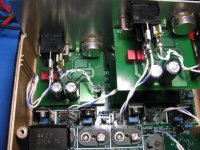
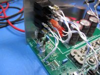
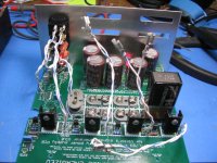
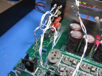
* The next 4 show the wiring going from the constant current sinks to the rocker switches for each Victor board, then from there to the Victor board power pins. The last 3 are close-ups of one Victor board wiring.
So on all 3 boards the CCS twisted pair feeds the center contacts of the rocker, then the right hand contacts have a short twisted pair that goes to the victor board power pins. Be careful about polarity, of course! Notice on those close-ups the blue wire with white stripe is the positive. Teh Victor power terminal closest to the pot he has marked as the +.
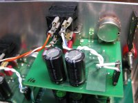
* A photo of another Victor board, showing the power wiring, same sort of thing.
Good deal, you have 3 Victor boards, same as mine!
So here are some photos that should help. I checked the nuts and washers on my Victor boards. They are the same size as 9mm dual pots, M7 with a pitch of 0.75mm. I have a bunch of those. Hopefully Victor hasn't changed pots, on his new boards, or if he has hopefully they have the same threads.
For the pots on my Victor board I had to use one washer in-between the pot and panel in the back, then a washer and nut on the front. That washer in the rear was needed to get the pot to line up perfectly mechanically since Victor has it back just a bit from the board edge.
Then on the ground nuts - at least on his older boards here - It took 3 flat washers in back between the ground nut socket and the panel to close the gap, then on the front I used the screw and external tooth lockwasher. My Victor boards actually came with all that - 3 or 4 flat washers, the ground screw, and the external tooth lockwasher. Let me know if yours is short any of that, I probably have it here.
Also, if you have his new boards, the spacing between that ground screw socket and panel may be different. You may have to mess with adding and removing washers a bit to his board to get it perfectly parallel to the mounting panel. Victor's boards were consistent, though. Once I figured out the right number of spacer washers to get them to sit flat it worked on all 3 boards.
Photos:
* The first two show the flat washer and nut in front of the Victor pot and one washer in back between the pot and rear of the panel.
* The next 3 show mounting of that terminal strip. I don't have mine connected - or the binding posts - because all the power is internal, off the power supply board. I have the posts and terminals there so folks could run power in via the front. They could also be used to run the power supply voltage out the front. You could even do something like build up that 4th constant current sink position and feed the output to the binding posts. That would give you a lab current source at any value you set if you happened to need a CCS for something. 🙂
That looks like I used a M3 stainless button head bolt 6mm or 8mm long for the terminal strip. I'll figure out which and send it. 🙂 The socket on those is M2 (2mm metric). They have those at Harbor Freight tools, a set of 3 foldable metric allen wrenches, English allen wrenches, and torx wrenches for $6 or so.
* The next 4 show the wiring going from the constant current sinks to the rocker switches for each Victor board, then from there to the Victor board power pins. The last 3 are close-ups of one Victor board wiring.
So on all 3 boards the CCS twisted pair feeds the center contacts of the rocker, then the right hand contacts have a short twisted pair that goes to the victor board power pins. Be careful about polarity, of course! Notice on those close-ups the blue wire with white stripe is the positive. Teh Victor power terminal closest to the pot he has marked as the +.
* A photo of another Victor board, showing the power wiring, same sort of thing.
Attachments
-
 IMG_4252.JPG227.7 KB · Views: 273
 -
 IMG_4270.JPG216.6 KB · Views: 273
 -
 IMG_4255.JPG287 KB · Views: 140
 -
 IMG_4254.JPG251.7 KB · Views: 136
 -
 IMG_4253.JPG275.3 KB · Views: 136
 -
 IMG_4256.JPG365.4 KB · Views: 159
 -
 IMG_4257.JPG312.4 KB · Views: 143
 -
 IMG_4258.JPG261.1 KB · Views: 127
 -
 IMG_4259.JPG256.1 KB · Views: 124
 -
 IMG_4260.JPG266.8 KB · Views: 126
Last edited:
- Status
- Not open for further replies.
- Home
- Design & Build
- Equipment & Tools
- A case and power supply for Victor's low THD oscillators