agdr,
It is coming along nicely. Looks like you are solving all the issues too.
Does victor make the other oscillators? That is the 11K and a 100 Hz or Richard, if you go lower than 100 Hz how low would you go? below 50/60 Hz power, i.e., 20 Hz or do you go just above it say 70, 80, or 90 Hz?
@ agdr,
BOM for the preferred BOM or individual items that you think are best, can you mark them with asterrisk or maybe a "+" sign. That would help folks who are not going to read through everything you've done here.
That way someone won't buy both DPST and SPST switches and for those who maybe challenged by following guidelines see that non-highlithed items are what is included, for example:
"This is the non-highlighted item the one that is in price."
Sometimes it helps to state the obvious, for guys like me.
Last edited:
Does victor make the other oscillators?
Well there is good timing! 🙂 I actually exchanged PM yesterday and this morning with Victor for the first time. I ordered an 11kHz board from him. Sounds like he makes them as a special-order that takes a couple of weeks on his end. Victor said that he can make a 100Hz board too, but there is the "intertia" issue he mentioned in the big thread which leads to some changes. I've decided to hold off on the 100Hz board until I look into the details a bit more, and was planning to PM Richard Marsh to get his thoughts. I'm not sure if Richard has modded or bought boards for those frequencies yet. I let Victor know about this thread too.
Yeah, I agree that staying away from the power line fundamental - or any of the first few harmonics - would be a good idea. In fact, as I typed that I just realized 100Hz would be the 2nd harmonic for 50Hz power. Maybe 90Hz or 110Hz would be better in general? They would still miss the 120Hz 2nd here in the US too. Richard, if you should read this post, what do you think?
Excellent idea on the BOM marking, probably a "+". I will add that. I was kind of concerned that someone might just order the whole BOM quickly without realizing that most of it is alternative choices.
Last edited:
I knew Victor will make other freqs as he has done so for others i know. yes, the 100Hz as a low freq would not work for everyone..... but Victor makes to order for each person. If he made a batch of them, then maybe 40 or 90 etc would work for everyone. We still need (or some of us) a chassis which will hold up to 4 of Victors boards.
THx-Richard
THx-Richard
Richard - yep, thinking about it some more, there probably isn't a single low frequency number that would be best for both 50Hz and 60Hz line frequency.
I agree that 100Hz is great for the 60Hz line here in the US. Good spacing away from both the fundamental and the 120Hz 2nd. 100Hz is a decade number which may have some math advantages too. For the 50Hz worldwide power I could think of several possibilities like 70Hz, 90Hz, etc. Probably best to let folks pick that one on their own. At least the board holes in the panel are the same! Folks can easily change the "100Hz" lettering with that free front panel designer program at FPE.
Speaking of which, my 4-board test panel is well under way. FPE sent the confirm of receiving the Hammond blank panel on Wednesday. Estimated completion Tuesday, then I get to watch the painfully slow 5-6 days ground shipping crawl via UPS tracking from Seattle to Texas. I've suggested to FPE a couple of times they should make USPS priority mail an option for these small one-off test panel orders. For the same price the panel could be here in 2 days rather than 5 or 6.
Hey on the 100Hz board and that long settling time ("intertia") that Victor keeps mentioning. Was a way to speed that up ever found in the (later part of) the big thread? No big deal either way. If I have to wait 5 minutes for it to stabilize so be it.
In power board news if anyone should have interest in that one, I haven't had a chance to mess with my power supply board layout any more. It hit me though that I could put power distribution busses under that otherwise "blank" section that will slide under the bottom two Victor board for the 2 case screw holes. I can put a set of power line holes near each board, then have traces go back to holes near the binding posts. That would eliminate the need for the two solder lugs. I'm also hatching a low battery LED circuit that could be optionally populated with an LED on the front panel part of the PCB. Just a filtered zener feeding an inverter circuit to warn when the total battery voltage goes below 38Vdc or so with a regulator or 35Vdc for binding post feed. Might even find a slick way to use a green/red bi-color LED to show both "on" and low battery.
Last edited:
It fits!
The 4 board front panel arrived from FPE today and it looks like I nailed it. 😀 The whole thing fits perfectly. The one thing I might do is add 1mm to the width of the four switch holes. I used the datasheet recommended width for panels 1.5mm to 2mm (the Hammond is 1.6mm). It does take some significant finger pressure to get them in, but nice and solid once in.
I'll go ahead and zip up a file with the FPE CAD files for the 4 hole and 2 hole and post here in a couple of days. I'm not going to do a test panel on the 2 hole since it is just the 4 hole that I deleted the top parts from the CAD file. Really nothing there that can get screwed up. I'll also post a file with instructions on exactly how to submit the CAD files to Front Panel Express (or Schaeffer in the EU) and instructions for mailing one of the blank panels from the box to them.
I'm not going to do any group buy with these panels since there is very little discount, 10% for 10 boards, which would then get eaten up with their shipping cost to me and the shipping costs to get the blank panels to them. Plus anyone interested in this panel may want to modify the text to their liking, which is easily done in that free Front Panel Designer Program.
I discovered why Victor includes those four washers on the ground bolt. They are needed to properly space the board to the panel. So the correct sequence is ground bolt - external tooth lockwasher (Victor includes) - the panel - the four washers - and then Victor's board.
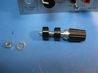
Then on the pot where Victor includes a nut and washer I discovered the washer needs to be left off, but the nut should be left on for proper spacing. That means you need to get another nut if you want to secure the panel to pot (recommended to ground the pot shaft and keep hand capacitive coupling from effecting things). Its the same nut as on a 9mm pot, so just buy a Mouser #652-PTD902-2020KA103 pot for $1.81, throw away the pot and keep the nut. 🙂 So the correct sequence here for the pot is: external nut on the panel face - washer that Victor included - the panel - the nut that victor included - the pot.
Victor told me yesterday that my 11kHz board shipped! I should have that to mount in a couple of weeks.
The photos below...
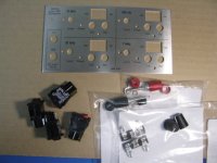
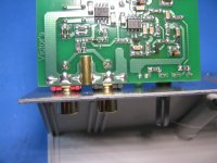
* The blank panel from FPE and parts from Mouser. Those are the DPST versions of the switches now. The Hammond panels have protective film on one side which I left in place when I mailed the panel to FPE, then gave them instructions to use that side. Arrived like this in just perfect condition. No scratches or any other evidence of the milling and engraving process.
* The next three show the panel with the two clam shell halves in place. Looks like I did leave enough room at the edges between the case and the text. In the middle photo it looks like the text engraving is skipping in places and not solid black. That isn't the case at all, just a lighting effect on the photo and due to the engraving having some depth, which also messes with the photo. The text engraving and straight black lines all came out solid black and look just terrific.
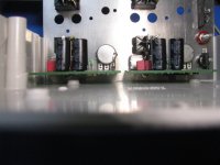
* The next two shows the fitment of Victor's boards on the panel. You can see the gap between the ground nut on Victors board and the case, that requires those four spacing washers that Victor includes. The washer Victor includes with the pot should be left off, but the pot nut should be left on to properly space the pot to the panel.
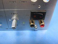
* The next shows the order the binding posts parts assemble. Note that the binding post itself has a metal D at the base that would fit in the panel D hole. The two insulators for the post have a "socket" for the metal D and reproduce that as a plastic D. You must use the insulators, even on the ground post, since the post ground is not the same as the ground screw ground which is the panel ground, as per postings above.
* The next two show the final product mounted in the case - without the 11kHz and 100Hz of course. On the rear shot you can see the two terminal solder lug strip mounted.
* The final one shows the clearance between the case-bottom screw bosses and the boards. Should be enough room for the power board and the mounting screws.
Congratulations again to Victor for the excellent oscillator board design!
The 4 board front panel arrived from FPE today and it looks like I nailed it. 😀 The whole thing fits perfectly. The one thing I might do is add 1mm to the width of the four switch holes. I used the datasheet recommended width for panels 1.5mm to 2mm (the Hammond is 1.6mm). It does take some significant finger pressure to get them in, but nice and solid once in.
I'll go ahead and zip up a file with the FPE CAD files for the 4 hole and 2 hole and post here in a couple of days. I'm not going to do a test panel on the 2 hole since it is just the 4 hole that I deleted the top parts from the CAD file. Really nothing there that can get screwed up. I'll also post a file with instructions on exactly how to submit the CAD files to Front Panel Express (or Schaeffer in the EU) and instructions for mailing one of the blank panels from the box to them.
I'm not going to do any group buy with these panels since there is very little discount, 10% for 10 boards, which would then get eaten up with their shipping cost to me and the shipping costs to get the blank panels to them. Plus anyone interested in this panel may want to modify the text to their liking, which is easily done in that free Front Panel Designer Program.
I discovered why Victor includes those four washers on the ground bolt. They are needed to properly space the board to the panel. So the correct sequence is ground bolt - external tooth lockwasher (Victor includes) - the panel - the four washers - and then Victor's board.
Then on the pot where Victor includes a nut and washer I discovered the washer needs to be left off, but the nut should be left on for proper spacing. That means you need to get another nut if you want to secure the panel to pot (recommended to ground the pot shaft and keep hand capacitive coupling from effecting things). Its the same nut as on a 9mm pot, so just buy a Mouser #652-PTD902-2020KA103 pot for $1.81, throw away the pot and keep the nut. 🙂 So the correct sequence here for the pot is: external nut on the panel face - washer that Victor included - the panel - the nut that victor included - the pot.
Victor told me yesterday that my 11kHz board shipped! I should have that to mount in a couple of weeks.
The photos below...
* The blank panel from FPE and parts from Mouser. Those are the DPST versions of the switches now. The Hammond panels have protective film on one side which I left in place when I mailed the panel to FPE, then gave them instructions to use that side. Arrived like this in just perfect condition. No scratches or any other evidence of the milling and engraving process.
* The next three show the panel with the two clam shell halves in place. Looks like I did leave enough room at the edges between the case and the text. In the middle photo it looks like the text engraving is skipping in places and not solid black. That isn't the case at all, just a lighting effect on the photo and due to the engraving having some depth, which also messes with the photo. The text engraving and straight black lines all came out solid black and look just terrific.
* The next two shows the fitment of Victor's boards on the panel. You can see the gap between the ground nut on Victors board and the case, that requires those four spacing washers that Victor includes. The washer Victor includes with the pot should be left off, but the pot nut should be left on to properly space the pot to the panel.
* The next shows the order the binding posts parts assemble. Note that the binding post itself has a metal D at the base that would fit in the panel D hole. The two insulators for the post have a "socket" for the metal D and reproduce that as a plastic D. You must use the insulators, even on the ground post, since the post ground is not the same as the ground screw ground which is the panel ground, as per postings above.
* The next two show the final product mounted in the case - without the 11kHz and 100Hz of course. On the rear shot you can see the two terminal solder lug strip mounted.
* The final one shows the clearance between the case-bottom screw bosses and the boards. Should be enough room for the power board and the mounting screws.
Congratulations again to Victor for the excellent oscillator board design!
Attachments
-
 IMG_3240.JPG155.6 KB · Views: 403
 -
 IMG_3258.JPG143.5 KB · Views: 246
 -
 IMG_3261.JPG152.7 KB · Views: 265
 -
 IMG_3259.JPG169.4 KB · Views: 232
 -
 IMG_3253.JPG162.6 KB · Views: 159
 -
 IMG_3250.JPG154.7 KB · Views: 220
 -
 IMG_3248.JPG182.6 KB · Views: 393
 -
 IMG_3247.JPG148.6 KB · Views: 389
 -
 IMG_3242.JPG151.4 KB · Views: 395
 -
 IMG_3241.JPG160.5 KB · Views: 403
Last edited:
I think this will work for me quit nicely. How does one get the panel from you now?
PM sent. 🙂
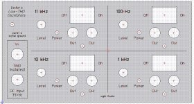
Panel CAD files for 1, 2 or 4 Victor boards and submission instructions
Below in the zip file are the CAD files for the panels and instructions on how to submit them to Front Panel Express here in the US or Schaeffer AG in Germany for drilling and engraving. The zip also includes the JPG screen captures below of the panels.
The zip file contains the CAD files for a 1, 2, or 4 Victor oscillator board panel. The 2 and 4 board panels are for the Hammond 1598 series of cases, as per the posts above, while the single board panel is for a Box Enclosures B3-080 case. The submission instructions in the zip file has all the details. The instructions are assuming that a blank panel from the case will be mailed to FPE or Schaeffer rather than using their own stock. I've done a few of these now for various projects and sending in the blank gives the best result.
I've made a few minor changes from the test panel I had fabricated in the post #45 above:
* Victor has let me know via PM that the hole to the left of the pot for a pot locator tab in his mechanical diagram is no longer needed. He has switched pot manufacturers and says he will revise his mechanical diagram. I was wondering about that since neither one of my boards had that tab on the pot! Those holes have been removed in all these CAD files. So one less hole that needs to be drilled for each one of Victor's boards.
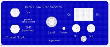
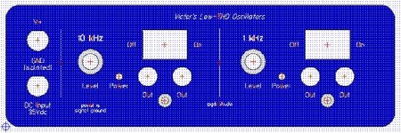
* I have added some words to make it more obvious that the DC power input ground is not connected to the panel, and that the panel is in fact signal ground. I've added "isolated" to the DC input ground text and added text that says "panel is signal ground". I'm just concerned that someone will use a lab supply that is also powering the device under test, or have its ground common with whatever is power the DUT. Whatever supply is used to power the Victor boards must be isolated and dedicated (or use batteries!).
* I noted in post #45 that the four switches take quite a bit of finger pressure to snap in using the datasheet hole dimensions. I've spoken with the manufacturer and that is apparently by design. The resulting clearances between switch body and panel are correct. Regardless I've increased the hole with by 0.1mm to 19.5mm from the previous datahseet 19.4mm number for a 1.6mm thick panel. I've found the best way to snap them in is do one side first, down flush with the panel, which leaves the switch wedged in the hole at a 30 degree or so angle. THEN snap in the other side. Don't try to snap in both sides at once. The plastic "springs" on the ends of the switch are too stiff for that. Be sure to support the panel from behind with a finger to prevent any bending.
If anyone else builds up one of these panels/cases please post photos! 🙂
I haven't had time to do any further work on an external/internal power board. I'm still planning on making and posting one eventually.
Below in the zip file are the CAD files for the panels and instructions on how to submit them to Front Panel Express here in the US or Schaeffer AG in Germany for drilling and engraving. The zip also includes the JPG screen captures below of the panels.
The zip file contains the CAD files for a 1, 2, or 4 Victor oscillator board panel. The 2 and 4 board panels are for the Hammond 1598 series of cases, as per the posts above, while the single board panel is for a Box Enclosures B3-080 case. The submission instructions in the zip file has all the details. The instructions are assuming that a blank panel from the case will be mailed to FPE or Schaeffer rather than using their own stock. I've done a few of these now for various projects and sending in the blank gives the best result.
I've made a few minor changes from the test panel I had fabricated in the post #45 above:
* Victor has let me know via PM that the hole to the left of the pot for a pot locator tab in his mechanical diagram is no longer needed. He has switched pot manufacturers and says he will revise his mechanical diagram. I was wondering about that since neither one of my boards had that tab on the pot! Those holes have been removed in all these CAD files. So one less hole that needs to be drilled for each one of Victor's boards.
* I have added some words to make it more obvious that the DC power input ground is not connected to the panel, and that the panel is in fact signal ground. I've added "isolated" to the DC input ground text and added text that says "panel is signal ground". I'm just concerned that someone will use a lab supply that is also powering the device under test, or have its ground common with whatever is power the DUT. Whatever supply is used to power the Victor boards must be isolated and dedicated (or use batteries!).
* I noted in post #45 that the four switches take quite a bit of finger pressure to snap in using the datasheet hole dimensions. I've spoken with the manufacturer and that is apparently by design. The resulting clearances between switch body and panel are correct. Regardless I've increased the hole with by 0.1mm to 19.5mm from the previous datahseet 19.4mm number for a 1.6mm thick panel. I've found the best way to snap them in is do one side first, down flush with the panel, which leaves the switch wedged in the hole at a 30 degree or so angle. THEN snap in the other side. Don't try to snap in both sides at once. The plastic "springs" on the ends of the switch are too stiff for that. Be sure to support the panel from behind with a finger to prevent any bending.
If anyone else builds up one of these panels/cases please post photos! 🙂
I haven't had time to do any further work on an external/internal power board. I'm still planning on making and posting one eventually.
Attachments

Last edited:
Lost it. Try again, please.
Resent. 🙂 It was still in my "sent" box. My previous PM may have been too long and never sent properly. When I copied it just now from the "sent" copy into a new PM and hit "send" the system came back with "too long 7000 characters, 5000 max, please shorten". Hmmm.... I didn't get that the first time, hence that copy in my sent folder. Strange stuff. Looks like my PM may have been too long and broke the system. Sorry about that! I've broken it up into 2 different PMs this time.
Last edited:
Where on eBay can I obtain Victor's PCB's
Where on eBay can I obtain Victor's 1kHz and 10kHz oscillators? 😕
Where on eBay can I obtain Victor's 1kHz and 10kHz oscillators? 😕
Following this thread for case ideas mostly .... At this stage I'll just use a Box Enclosures B4 because I'm using them for other projects so that's convenient.
opc has just announced a high voltage adjustable regulator that would likely be ideal for these oscillators - see here for more info http://www.diyaudio.com/forums/vend...-here-bal-bal-se-se-lpuhp-68.html#post4242273 looks like he'll be able to offer assembled PCBs for those who aren't able to do the SMD work too.
Chris
hochopeper - the B4 case should work just fine! You could start with the CAD file I posted for the B3 case and then modify from there with the free Front Panel Express software. Just remember to account for that center-screw extrusion that runs the length of the case right in the middle at the bottom. The B3 doesn't have that. It looks like it would be possible to fit two of Victors boards side by side in the B4 too. It is slightly wider than the Hammond case.
Interesting about opc's new power supply! I hadn't seen his post yet. The does sound perfect for this project. That AD regulator chip is listed at 200mA max. It shouldn't have any trouble with 1-4 of Victor's boards, assuming opc has it well heat sinked. opc probably means the LM317HV as the pre-regulator rather than just the LM317.
Interesting about opc's new power supply! I hadn't seen his post yet. The does sound perfect for this project. That AD regulator chip is listed at 200mA max. It shouldn't have any trouble with 1-4 of Victor's boards, assuming opc has it well heat sinked. opc probably means the LM317HV as the pre-regulator rather than just the LM317.
Last edited:
hochopeper - the B4 case should work just fine! You could start with the CAD file I posted for the B3 case and then modify from there with the free Front Panel Express software. Just remember to account for that center-screw extrusion that runs the length of the case right in the middle at the bottom. The B3 doesn't have that. It looks like it would be possible to fit two of Victors boards side by side in the B4 too. It is slightly wider than the Hammond case.
Yeah I had a look at that last night as I was fiddling with a phono stage that I'm putting into another B4, two will fit comfortably side by side and plenty of room for PSU. At this stage I think I'll just drill the front panels myself but I do have a few other things I'm putting into B4 enclosures so I might do FPE designs up and order them when it comes time to make things look nicer than my rough hand drilled work.
Interesting about opc's new power supply! I hadn't seen his post yet. The does sound perfect for this project. That AD regulator chip is listed at 200mA max. It shouldn't have any trouble with 1-4 of Victor's boards, assuming opc has it well heat sinked. opc probably means the LM317HV as the pre-regulator rather than just the LM317.
I think he's used LM317 before for high voltage regulators in the NTD1 circuit, I never looked at that circuit too closely but know that he did get it working. I'd expect that part of the circuit to be similar to what he did on that old design but now with a second regulator following it. I think he mentioned that for heatsinking he's mounting them to an enclosure via thermal pad (no through hole components making a mess of the flat bottom surface) so hopefully they fit in my B4 between that bottom rib in the enclosure and one side and I can then just screw the PSU to the case. I've asked Owen for dimensions on the PSU board, that board is for 4 regs though, so might be able to chop part of it off since I'll only be using at most 2 of the regulators.
Chris
two will fit comfortably side by side and plenty of room for PSU.
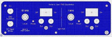
Here you go - CAD files below. 🙂 I'm glad you brought up the (Box Enclosures) B4-080 case. It really is a good solution for just 2 of Victor's boards.
One CAD file is with the 5 mounting screw holes (from the panel to the case) if a person is having FPE use their own 2mm material. The other is without the mounting holes if you are sending the blank panel from the B4 case into FPE, or drilling it yourself.
You can pull all the hole locations and sizes off these CAD files for home drilling with that free FPD program of theirs, from here:
Front Panel Express: Front Panel Design Software and CAD Conversion Service: Front Panel Designer
If anyone should want to try submitting this CAD file to Front Panel Express the submission instructions are the same as in the zip file with post #48.
Attachments
Last edited:
Hi,
I just recieved your 4 victor osc panel/box etal. Looks good. now I will be able to run the osc more easily than with jumpers wires everywhere and pcb laying on open area/bench.
Thank you,
Richard Marsh
I just recieved your 4 victor osc panel/box etal. Looks good. now I will be able to run the osc more easily than with jumpers wires everywhere and pcb laying on open area/bench.
Thank you,
Richard Marsh
I'm glad the package made it OK! The female quick disconnects should arrive on Saturday they say.
Last edited:
I think, you already have the solution in the blue part. There is no battle between the CCS's, because the shunt regs will balance it. If let's say the positive CCS feeds 35mA, then the positive shunt will take 10mA, the board 25mA. If the negative CCS would be badly adjusted to 37mA, the negative shunt simply takes 12mA. The negative CCS will be LM337.One way around that would be two CCS per Victor card, one on the positive wire and other on the negative (with the 100R's removed), but that probably isn't a great idea since one CCS will "win" on each card. A better solution would probably be use the CCS-per-card on the positive lead, but leave the 100R resistor in on the negative lead.
I'm certainly open to ideas on ways to work a CCS(es) into it all! 🙂 This one is a bit of a head scratcher, given the constraints of the TL431's on Victor's boards.
A CCS has high impedance by definition, it prevents battery noise from entering the board. Obviously it will be important to have a CCS on both sides.
Last edited:
I think, you already have the solution in the blue part. There is no battle between the CCS's, because the shunt regs will balance it. If let's say the positive CCS feeds 35mA, then the positive shunt will take 10mA, the board 25mA. If the negative CCS would be badly adjusted to 37mA, the negative shunt simply takes 12mA. The negative CCS will be LM337.
Hey good thoughts, but I think the lack of a ground return in the middle (the virtual ground between the two shunt regulators) would still mess it up. So if that negative LM337 CCS were at 37mA, there would be nowhere for the extra 37mA - 35mA = 2mA to go at the input to the postive CCS. The board's draw would be the same, 25mA, and the extra 2mA could not go out through the 35mA CCS.
But if instead of being fed with a single 35Vdc supply the incoming supply was +/-17.5 with a real ground in the middle, and if the middle tie point between the shunt regulators on Victor's board was attached to the same real ground rather than being the floating virtual ground, the extra 2mA would be returned to the negative power supply by the negative shunt regulator on the board.
Hmmm...... maybe that is an idea. Use a dual rail +/-17.5 (or just round it up to +/-18Vdc) and do a modification on victor's board to tie that center virtual ground point to the real ground. That would solve some things. Right now I have to have a note etched on the panel that the negative lead of the 35Vdc is floating and the panel is the actual ground, being tied to that center virtual ground point on each board. With a dual rail supply and the Victor board mod the grounds would all be the same. Or leave the single set of binding posts on the front panel for the 35Vdc, but the internal power supply could generate the +/-18Vdc. That would be especially easy since I was planning on using a voltage doubler set up to generate dual rails anyway, as in the O2 headphone amp's power supply. I was just going to use the rail-to-rail voltage but with this could use the center ground too. Then one pair of CCS per board. The CCS power dissipation may be low enough to use the TO-92 version of the LM317 and 337 for each.
Last edited:
- Status
- Not open for further replies.
- Home
- Design & Build
- Equipment & Tools
- A case and power supply for Victor's low THD oscillators