I use an commercial reg power supply ... no batteries to change/charge and always at full voltage forever. However, batteries can help if you have ground noise/loop issues. I havent had such problem with my power supply.
THx-RNMarsh
THx-RNMarsh
Alex & Richard - thanks for the feedback!
Hmmm. I haven't really liked the prospect of having to take the four case screws out to change the batteries either. I also have a couple of lab supplies around that would do the job. Probably a reasonable assumption that most folks who would be using Victor's boards also do have power supplies to run them with. I agree that the life of the 9V cells would not be very good vs. just having the oscillators powered from an AC supply. Pretty easy for hours to go by quickly when using test equipment (or simply forgetting to turn it off, which I'm guilty of all the time).
Maybe the best way to go is just the box and drilled panel with Victor's boards but no batteries. Instead have a couple of panel-mounted binding posts, the kind with a banana plug socket in the middle, for power input. Then the user could use external batteries or a power supply at their discretion. The power supply switches for the boards were going to be panel mounted anyway. Just wire the binding posts to switch(es) to Victor's boards internally. I could still whip up the LM317HV/TL783 regulator circuit board (current source or voltage source again but no batteries) that fits in the internal case slot. The circuit board could be used optionally if someone wanted, such as with the external batteries.
This would solve another problem. Up until now I've been using the measurements Victor gives for the board. Last night I spent some time with a caliper measuring the extent of the pot's metal housing and the RCA jacks housing, then plugging that into the CAD program. Those upper upside-down boards won't fit after all. The pots just barely obstruct each other by 2mm or so. If the case were 3-4mm taller it would work, but I've yet to find a taller extruded case. So it looks like it is back to just two of Victor's boards side by side (rightside up) in a 160mm wide case.
Given that, the case could be a wide-but-short Box Enclosures B4-080, 160mm wide and 80mm deep (Victors boards are 50mm deep). $19 each at Allied Electronics. Then two of them could be used for 4 boards. If the cases simply had the binding posts for power the lab supply could go to one box then banana plug cables used to feed the second box from the first. Or the case could still be the Hammond 160 x 160 with the (optional) circuit board including the rgulator & layout for the batteries, if someone did want to populate that, but just the regulator section alone could be populated & fed from the binding posts. Hammond cases are probably going to be easier to find in stock around the world than Box Enclosures.
Last edited:
Standalone battery/voltage-doubler board for a box enclosures B4-080 case
Here is an idea that goes with the above, having Victor's boards in a case with no batteries or AC supply, just binding posts and the optionally-populated regulator circuit.
I'm splitting the previous battery section out as a stand-alone battery board here that could either be used case-less on four 4mm standoffs, or put in a B4-080 Box Enclosures case. Using it without a case solves the problem of easily getting to the batteries to change them. The 6th battery is now on edge and held in place with a Keystone 80 9V battery clip.
I've taken Alex' suggestion and removed all the diodes but the final one. He is right - with a battery stack touching any one cell to their terminals reversed should just subtract that much from the total. The important thing is that the voltage sum be the correct polarity, hence the one remaining series diode. Since there is just one diode drop now that can be a common 1N4002.
The board also has the layout for a voltage doubler AC supply. With the AC supply in a separate case now like this the chances of not getting power line harmonics into the oscillator board should go way up.
Just wire from the battery board terminals to the binding posts on the case that contains Victor's boards and away it goes. 🙂
Attachments

Last edited:
Back to 4 (or 2) Victor oscillator boards in a single 1598EBK or 1598REBK case
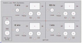
Another iteration. 🙂 Back to four, or just 2, of Victor's oscillator boards in one single case.
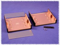
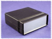
It hit me that with the batteries or AC supply external now there would be no need for the card slots in the extruded aluminum case. Going through the list of Hammond's cases I found the one below, the $16 (Mouser & Digikey) 1598EBK plastic case with metal end panels, or its cousin the RF shielded conductive-coated plastic 1598REBK. The last picture below is the inside of the RF shielded version showing the copper coating on the inside.
The case is 86 mm tall, more than enough for two of Victor's boards stacked on top of each other (right side up) at 27 mm each, unlike any of the extruded cases at 48 mm or so.
The binding posts for the power input are on the lower left. Each board has a power switch in the upper left allowing them to be turned on individually. The optional current source or voltage regulator board could be bolted to the back panel. I could fit it on the front panel under the switches, but I'm hesitant to heat up the front panel and the area around the oscillator boards - might encourage drift. The case wouldn't help heat sink on this one, being plastic.
The case comes with 4 rubber mounting feet. The cover screws apparently go into a threaded metal insert in the opposite clam shell plastic. No plastic threads stripping out with multiple cover openings over time. This panel design totals up to $49 for the 4 board version on Front Panel Express' CAD program ordering tab. The two board version clocks in at $39.11.
Another iteration. 🙂 Back to four, or just 2, of Victor's oscillator boards in one single case.
It hit me that with the batteries or AC supply external now there would be no need for the card slots in the extruded aluminum case. Going through the list of Hammond's cases I found the one below, the $16 (Mouser & Digikey) 1598EBK plastic case with metal end panels, or its cousin the RF shielded conductive-coated plastic 1598REBK. The last picture below is the inside of the RF shielded version showing the copper coating on the inside.
The case is 86 mm tall, more than enough for two of Victor's boards stacked on top of each other (right side up) at 27 mm each, unlike any of the extruded cases at 48 mm or so.
The binding posts for the power input are on the lower left. Each board has a power switch in the upper left allowing them to be turned on individually. The optional current source or voltage regulator board could be bolted to the back panel. I could fit it on the front panel under the switches, but I'm hesitant to heat up the front panel and the area around the oscillator boards - might encourage drift. The case wouldn't help heat sink on this one, being plastic.
The case comes with 4 rubber mounting feet. The cover screws apparently go into a threaded metal insert in the opposite clam shell plastic. No plastic threads stripping out with multiple cover openings over time. This panel design totals up to $49 for the 4 board version on Front Panel Express' CAD program ordering tab. The two board version clocks in at $39.11.
Attachments
Last edited:
OK I'll sign on for the four osc panel.... dont have to jumper my external regulated power supply from box to box. Price on everything seems reasonable to me.
BTW - I was thinking of mounting the osc pcb on vertically on its edge via a couple L-brackets.... can cram a lot of those pcb internally that way. What do you think about that way?
THx-RNMarsh
BTW - I was thinking of mounting the osc pcb on vertically on its edge via a couple L-brackets.... can cram a lot of those pcb internally that way. What do you think about that way?
THx-RNMarsh
Last edited:
Somebody makes a slotted aluminum case and boards for older hard drives. If I remember correctly you could make your sides various lengths/hights if you will.they slide into the top and bottom rails.
s or ends
s or ends
Fully (metal) optional AC power supply addition
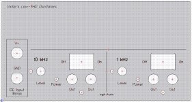
Good thoughts! I had missed that. With the taller case vertical board mounting would work, as SyncTronX posted back in #6. I just tried it with the boards vertical and the on/off switch for each at the top of each board. Unfortunately still just 4 would fit the way things work out. Looks like what happens is that even though the panel is wider than tall it winds up with some wasted space vertically.
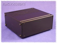
It looks like it would be possible to stack more vertically in the Hammond RMCV9038BK1 2U half-width short-depth (8") rack case, which can be used without the rack ears for desktop use as in the picture below. Looks like 6 boards would fit vertically with 5mm or so to clear. Using the full-width short-depth cousin to that, the RMCV19038BK1, it would be possible to get a whopping 11 or 12 of Victors boards in vertically. Those cases are pricey though, $84 at Newark for the half rack and $88 at Digikey for the full, although they are built like tanks and worth the money. I'm not going to pursue those right now unless there is a lot of interest out there in 6 or 12 ov Victor's boards, but they are something to keep in mind for a "XL" future version. 🙂
In some news on the design in post #24 above I've put space in the lettering between the number and the "Hz" labels, below. I think it looks a little better. And another idea! - it looks like a Box Enclosures B3-080 100mm x 80mm deep metal extruded case here could fit inside the Hammond 1598EBK plastic case in the back to house an AC power supply. The front panel of the B3-080 would be left off and instead bolt right to the back panel of the Hammond case. The box would sit on the back two 3mm plastic "PCB support" nubs in the 1598EBK case. With the voltage doubler power supply parts totally enclosed in a Faraday case like that I wouldn't have any concerns about the power line harmonics getting into the oscillators.
The power supply addition would make great use of the rest of that plastic Hammond case, since Victor's board are only 50mm deep and the case is 145mm deep. This would also solve a likely problem of the plastic case being too light and moving around on the desk. The power supply parts would add some weight to the back.
The power supply part would be completely optional. The front panel would have the binding posts regardless. The power switches are already SPDT with one half unused. With the power supply those could change to the on-off (in the middle) - on type. In one "on" position for each board you get the binding posts, in the other you get the internal power supply, and middle is off.
BTW - I was thinking of mounting the osc pcb on vertically on its edge via a couple L-brackets.... can cram a lot of those pcb internally that way. What do you think about that way?
Good thoughts! I had missed that. With the taller case vertical board mounting would work, as SyncTronX posted back in #6. I just tried it with the boards vertical and the on/off switch for each at the top of each board. Unfortunately still just 4 would fit the way things work out. Looks like what happens is that even though the panel is wider than tall it winds up with some wasted space vertically.
It looks like it would be possible to stack more vertically in the Hammond RMCV9038BK1 2U half-width short-depth (8") rack case, which can be used without the rack ears for desktop use as in the picture below. Looks like 6 boards would fit vertically with 5mm or so to clear. Using the full-width short-depth cousin to that, the RMCV19038BK1, it would be possible to get a whopping 11 or 12 of Victors boards in vertically. Those cases are pricey though, $84 at Newark for the half rack and $88 at Digikey for the full, although they are built like tanks and worth the money. I'm not going to pursue those right now unless there is a lot of interest out there in 6 or 12 ov Victor's boards, but they are something to keep in mind for a "XL" future version. 🙂
In some news on the design in post #24 above I've put space in the lettering between the number and the "Hz" labels, below. I think it looks a little better. And another idea! - it looks like a Box Enclosures B3-080 100mm x 80mm deep metal extruded case here could fit inside the Hammond 1598EBK plastic case in the back to house an AC power supply. The front panel of the B3-080 would be left off and instead bolt right to the back panel of the Hammond case. The box would sit on the back two 3mm plastic "PCB support" nubs in the 1598EBK case. With the voltage doubler power supply parts totally enclosed in a Faraday case like that I wouldn't have any concerns about the power line harmonics getting into the oscillators.
The power supply addition would make great use of the rest of that plastic Hammond case, since Victor's board are only 50mm deep and the case is 145mm deep. This would also solve a likely problem of the plastic case being too light and moving around on the desk. The power supply parts would add some weight to the back.
The power supply part would be completely optional. The front panel would have the binding posts regardless. The power switches are already SPDT with one half unused. With the power supply those could change to the on-off (in the middle) - on type. In one "on" position for each board you get the binding posts, in the other you get the internal power supply, and middle is off.
Attachments
Last edited:
I'm glad there is some interest in this! 🙂
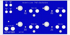
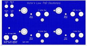
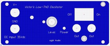
Here is another iteration. The front and rear panels are listed as "brushed aluminum" with no mention of anodization. I'm going to skip the 0.25mm countersinking then, which was there to cut through the anodization layer for a better electrical connection. I see that Victor is including an external-tooth lock washer on the ground screw on each board, which should be sufficient to pierce the surface oxidation on brushed aluminum.
Under the nut on the pot I would recommend using this stuff. It has microscopic abrasive particles that cut through the aluminum oxide layer. Works great. I've seen wiring coming out of decade-old outdoor circuit breakers that were dipped in the stuff looking brand new.
Since the panel is brushed aluminum I've also changed the text engraving fill to black. Front panel express has all sorts of fill colors though that can be selected in the FPD CAD program.
Reading through the Hammond literature a bit more I've discovered that there is also an even cheaper Hammond box of the same type (160mm x 160 x 3.38 inches high), the 1598ESGY with grey plastic with aluminum end panels, for just $11.50 at Mouser and Digikey. The $15.30 1598EBK or 1598EGY (black, grey) that I was looking at before apparently adds being flame retardant and also comes in black. Then the $33 1598REBK adds the RF shield coating on the inside. I should have one of them from Mouser on Tuesday and can then send the panel into Front Panel Express for drilling. I had some concern that the panel was only supported at the edges since they are just 1.6mm thick. I found a higher resolution photo of the inside showing that the panels are supported in groves all the way around. Should be nice and solid.
Double checking the measurements I realized that I had the whole bunch of boards 8mm too far to the right. The revised panel is below. The on/off switches are now above the board they control, which is a good thing because I always forget about the difficulty in breaking DC. Turns out there is almost nothing out there (in stock anyway) in a miniature toggle switch over 30V DC breaking rating. Victor's board needs 35Vdc of course. I found just one NKK switch rated at 48Vdc, but only stocked at Mouser, and only 50 of them. Lol, not going to do that to myself on sole source orphan parts.
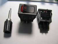
Rocker switches seem to be available in higher DC breaking rating. I've settled on Mouser #691-62116919-0-9-V (Carling 62116919-0-9-V) which is only $1.38 each with lots of them stock. The switch is also in stock at Digikey, Allied, Newark and all sorts of other vendors. This is a fairly big switch rated at 250Vdc breaking and 4A. There really doesn't seem to be much out there between this and the 30Vdc miniature toggles. Nice looking switch though, probably more pro looking than a bat handle toggle anyway, here (opens pdf, the red lettering on black one on the left). The switch uses quick disconnects, these guys, which could just be soldered to.
Here is another iteration. The front and rear panels are listed as "brushed aluminum" with no mention of anodization. I'm going to skip the 0.25mm countersinking then, which was there to cut through the anodization layer for a better electrical connection. I see that Victor is including an external-tooth lock washer on the ground screw on each board, which should be sufficient to pierce the surface oxidation on brushed aluminum.
Under the nut on the pot I would recommend using this stuff. It has microscopic abrasive particles that cut through the aluminum oxide layer. Works great. I've seen wiring coming out of decade-old outdoor circuit breakers that were dipped in the stuff looking brand new.
Since the panel is brushed aluminum I've also changed the text engraving fill to black. Front panel express has all sorts of fill colors though that can be selected in the FPD CAD program.
Reading through the Hammond literature a bit more I've discovered that there is also an even cheaper Hammond box of the same type (160mm x 160 x 3.38 inches high), the 1598ESGY with grey plastic with aluminum end panels, for just $11.50 at Mouser and Digikey. The $15.30 1598EBK or 1598EGY (black, grey) that I was looking at before apparently adds being flame retardant and also comes in black. Then the $33 1598REBK adds the RF shield coating on the inside. I should have one of them from Mouser on Tuesday and can then send the panel into Front Panel Express for drilling. I had some concern that the panel was only supported at the edges since they are just 1.6mm thick. I found a higher resolution photo of the inside showing that the panels are supported in groves all the way around. Should be nice and solid.
Double checking the measurements I realized that I had the whole bunch of boards 8mm too far to the right. The revised panel is below. The on/off switches are now above the board they control, which is a good thing because I always forget about the difficulty in breaking DC. Turns out there is almost nothing out there (in stock anyway) in a miniature toggle switch over 30V DC breaking rating. Victor's board needs 35Vdc of course. I found just one NKK switch rated at 48Vdc, but only stocked at Mouser, and only 50 of them. Lol, not going to do that to myself on sole source orphan parts.
Rocker switches seem to be available in higher DC breaking rating. I've settled on Mouser #691-62116919-0-9-V (Carling 62116919-0-9-V) which is only $1.38 each with lots of them stock. The switch is also in stock at Digikey, Allied, Newark and all sorts of other vendors. This is a fairly big switch rated at 250Vdc breaking and 4A. There really doesn't seem to be much out there between this and the 30Vdc miniature toggles. Nice looking switch though, probably more pro looking than a bat handle toggle anyway, here (opens pdf, the red lettering on black one on the left). The switch uses quick disconnects, these guys, which could just be soldered to.
Attachments
Last edited:
Yet another panel revision, with grouping.
Attachments
Last edited:
It fits! Test panel order out the door
I received the case and parts today from Mouser. It looks like everything is going to fit on the panel as measured.
I've just sent a panel order out to Front Panel Express. I'm going to send one of the blank panels from the case in for them to use. Hammond has one surface of each panel covered in protective paper, which is a nice touch. It takes FPE about a week to drill & engrave a panel, a week for UPS to get it to me, and 3 days for the panel blank to get to them in the first place. So with any luck I should have the panel back in about 2.5 weeks.
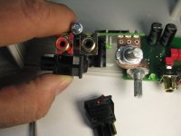
I'm going to change the "standard" switch in the BOM over to the DPST from the SPST (same size and looks the same, $0.20 more), which right now is the alternate. The DPST makes the wiring easy since a twisted pair then just goes from each switch to the header that plugs into Victor's board, as in the photo below. Then a twisted pair goes from each switch to the solder lugs. I've included a hole above the binding posts for mounting a good old-fashioned two terminal solder lug (also in the BOM) as a place to attach all the wires. One wire from each binding post to a lug, then one twisted pair from each switch to the lugs. Then solder up the lugs.
Important change: A problem just occured to me. The ground screw on each of Victor's boards is attached to the midpoint of the two TL431's that make the +/-15Vdc. That ground point is different from the V- terminal on the power input since it is on the other side of one of the 100R resistors. With the metal panel that ground screw point on each of the 2 or 4 boards is going to be connected together. That will work as long as the input is the 35Vdc, not a current source, with the 100R resistors on each board left in tact. To use a current source the plastic panel version of the case would have to be used to isolate the board grounds.
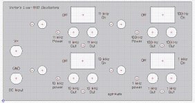
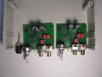
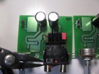
The photos below:
* The layout of two boards side-by-side and the binding posts, as they will fit on the panel.
* Depth of the switch. The lower two terminals will either have to be soldered or use right angle (flag) quick disconnects. I plan to solder all mine. Fastons are great in appliances but for this project solder is probably going to give the best connection. This switch is really an appliance switch.
* Closeup of the switch and binding post.
* Height of the switch body above the board RCA jacks.
* 3 pin header sockets.
I received the case and parts today from Mouser. It looks like everything is going to fit on the panel as measured.
I've just sent a panel order out to Front Panel Express. I'm going to send one of the blank panels from the case in for them to use. Hammond has one surface of each panel covered in protective paper, which is a nice touch. It takes FPE about a week to drill & engrave a panel, a week for UPS to get it to me, and 3 days for the panel blank to get to them in the first place. So with any luck I should have the panel back in about 2.5 weeks.
I'm going to change the "standard" switch in the BOM over to the DPST from the SPST (same size and looks the same, $0.20 more), which right now is the alternate. The DPST makes the wiring easy since a twisted pair then just goes from each switch to the header that plugs into Victor's board, as in the photo below. Then a twisted pair goes from each switch to the solder lugs. I've included a hole above the binding posts for mounting a good old-fashioned two terminal solder lug (also in the BOM) as a place to attach all the wires. One wire from each binding post to a lug, then one twisted pair from each switch to the lugs. Then solder up the lugs.
Important change: A problem just occured to me. The ground screw on each of Victor's boards is attached to the midpoint of the two TL431's that make the +/-15Vdc. That ground point is different from the V- terminal on the power input since it is on the other side of one of the 100R resistors. With the metal panel that ground screw point on each of the 2 or 4 boards is going to be connected together. That will work as long as the input is the 35Vdc, not a current source, with the 100R resistors on each board left in tact. To use a current source the plastic panel version of the case would have to be used to isolate the board grounds.
The photos below:
* The layout of two boards side-by-side and the binding posts, as they will fit on the panel.
* Depth of the switch. The lower two terminals will either have to be soldered or use right angle (flag) quick disconnects. I plan to solder all mine. Fastons are great in appliances but for this project solder is probably going to give the best connection. This switch is really an appliance switch.
* Closeup of the switch and binding post.
* Height of the switch body above the board RCA jacks.
* 3 pin header sockets.
Attachments

Last edited:
I don't think so, re: the supply.
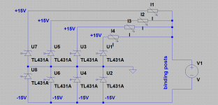
However there is one thing that has to be present, and that is one CCS per card.
That is a floating supply, each card is symmetrical around the derived ground point. As the cards are virtually the same in terms of supply and symmetry of the derived ground there should be no problem with one battery stack feeding all the cards.
Alan
However there is one thing that has to be present, and that is one CCS per card.
That is a good thought, I actually did have that written up while composing the post above at one point, but then spotted a problem and deleted it all. I've whipped up the example circuit below, leaving out the TL431 ref line set resistors for clarity. With one CCS per card (and Victor's 100R's removed) the positive TL431's are OK, but the negative ones still all wind up in parallel, pinned between the common ground and the negative feed, and will fight.
One way around that would be two CCS per Victor card, one on the positive wire and other on the negative (with the 100R's removed), but that probably isn't a great idea since one CCS will "win" on each card. A better solution would probably be use the CCS-per-card on the positive lead, but leave the 100R resistor in on the negative lead.
The ultimate solution would be one CCS per card with one separate isolated supply voltage for each, but too many parts and cost there for not much added benefit over just using the existing 100R's and a voltage source.
I do think it is important that the grounds for all four boards be tied together since that will happen anyway in any sort of typical usage scenario, through the other equipment and the device under test. So really not a good idea to go with the plastic front panel option to isolate the grounds.
I'm certainly open to ideas on ways to work a CCS(es) into it all! 🙂 This one is a bit of a head scratcher, given the constraints of the TL431's on Victor's boards.
Attachments
Last edited:
A single Victor board in a B3-080 case
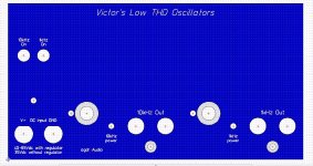
Here is a panel design for a single one of Victor's boards in a Box Enclosures B3-080 case.
On this one I've left room for the LM317HV/TL783 voltage regulator - or current source wiring, can use a current source if just one board - between the binding posts and the board. I'm much less concerned about oscillator drift from regulator heating with the panel bolted to this all-metal box. Plenty of heat sinking.
I've gone back to white (or any color) letting since the box enclosure cases are anodized various colors. I've added the countersinking back to cut through the anodization for a good electrical connection.
This one totals up to around $36 in the Front Panel Express CAD program. I'm probably not going to send this one out, but I'll post the CAD file once the 4 board panel is back (and I can verify the measurments) in case anyone wants to give it a try.
Attachments
Power supply board
Here is the latest stab at a power supply board. 🙂 This would be for some power options other than just running the front panel binding posts to a lab power supply.
Since the Hammond 1598EBK series of cases are clam shells with only two cover screws, it becomes practical again to have the batteries inside. Especially since the cover screws go into metal studs and are actually rated by Hammond for multiple cover removals. The aluminum Box Enclosure cases had 4 screws that are thread-forming, not a great thing for surviving many removals.
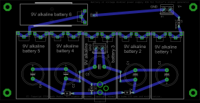
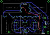
The board has places for six 9V batteries, a heat sink with a regulator, a back panel heat sinked regulator, holes for standoffs, holes for case mounting, and an AC-fed voltage doubler supply. The regulator can be wired as either a voltage source or current source again. All of this isn't used at once of course. Different parts can be populated to yield different configurations. The board is sized to fit in the rear portion of the 15989EBK case, behind Victor's boards.
The wiring options are:
* Use it as an external stand-alone caseless battery power supply board. Use four 3mm standoffs in the holes provided to just sit the board on a table. This configuration is easiest for changing batteries - no case to disassemble. The on-board heat sink with voltage regulator would be used. The rear edge regulator is left unpopulated, as are the AC supply parts.
* Use it as an external stand-alone caseless AC supply. Leave off the batteries, populate the voltage doubler circuit, and feed it with 24Vac from a wall transformer. Use the on-board heat sink with voltage regulator. The rear edge regulator is left unpopulated. Use four 3mm standoffs in the holes provided to just sit the board on a table.
* Use it as an internal battery powered supply board in the rear of the 1598EBK case, behind Victor's boards. The two case screws would have to be removed and the case clam shells separated each time the batteries have to be changed. The heat sink and associated regulator chip would be left off. Use the card-edge regulator chip which is heat sinked to the rear panel of the case. The AC voltage doubler parts are left off. The four standoff holes are not used. Instead the two case mounting holes are used to run screws into the two rear 3mm mounting studs in the case.
* Use it as an internal AC power supply board in the rear of the 1598EBK case, behind Victor's boards. The batteries are not populated but instead the AC voltage doubler circuit is. Feed it with a 24Vac wall transformer. The heat sink and associated regulator chip would be left off. Use the card-edge regulator chip which is heat sinked to the rear panel of the case. The four standoff holes are not used. Instead the two case mounting holes are used to run screws into the two rear 3mm mounting studs in the case. In addition to the one hole for heat sinking the voltage regulator, the rear panel would require a square hole for the 2.1mm AC power jack.
Once I get the designed finalized I'll send it out for fabrication. That should take a week and a week in the mail, so with any luck should show up about the same time as the panel from Front Panel Express. 🙂 If the board works as planned I'll then post the Gerbers.
Here is the latest stab at a power supply board. 🙂 This would be for some power options other than just running the front panel binding posts to a lab power supply.
Since the Hammond 1598EBK series of cases are clam shells with only two cover screws, it becomes practical again to have the batteries inside. Especially since the cover screws go into metal studs and are actually rated by Hammond for multiple cover removals. The aluminum Box Enclosure cases had 4 screws that are thread-forming, not a great thing for surviving many removals.
The board has places for six 9V batteries, a heat sink with a regulator, a back panel heat sinked regulator, holes for standoffs, holes for case mounting, and an AC-fed voltage doubler supply. The regulator can be wired as either a voltage source or current source again. All of this isn't used at once of course. Different parts can be populated to yield different configurations. The board is sized to fit in the rear portion of the 15989EBK case, behind Victor's boards.
The wiring options are:
* Use it as an external stand-alone caseless battery power supply board. Use four 3mm standoffs in the holes provided to just sit the board on a table. This configuration is easiest for changing batteries - no case to disassemble. The on-board heat sink with voltage regulator would be used. The rear edge regulator is left unpopulated, as are the AC supply parts.
* Use it as an external stand-alone caseless AC supply. Leave off the batteries, populate the voltage doubler circuit, and feed it with 24Vac from a wall transformer. Use the on-board heat sink with voltage regulator. The rear edge regulator is left unpopulated. Use four 3mm standoffs in the holes provided to just sit the board on a table.
* Use it as an internal battery powered supply board in the rear of the 1598EBK case, behind Victor's boards. The two case screws would have to be removed and the case clam shells separated each time the batteries have to be changed. The heat sink and associated regulator chip would be left off. Use the card-edge regulator chip which is heat sinked to the rear panel of the case. The AC voltage doubler parts are left off. The four standoff holes are not used. Instead the two case mounting holes are used to run screws into the two rear 3mm mounting studs in the case.
* Use it as an internal AC power supply board in the rear of the 1598EBK case, behind Victor's boards. The batteries are not populated but instead the AC voltage doubler circuit is. Feed it with a 24Vac wall transformer. The heat sink and associated regulator chip would be left off. Use the card-edge regulator chip which is heat sinked to the rear panel of the case. The four standoff holes are not used. Instead the two case mounting holes are used to run screws into the two rear 3mm mounting studs in the case. In addition to the one hole for heat sinking the voltage regulator, the rear panel would require a square hole for the 2.1mm AC power jack.
Once I get the designed finalized I'll send it out for fabrication. That should take a week and a week in the mail, so with any luck should show up about the same time as the panel from Front Panel Express. 🙂 If the board works as planned I'll then post the Gerbers.
Attachments
Last edited:
Using rechargeable batteries with the power board & note on the case
I had a question asked about using rechargeable 9V batteries with the power board layout above. They will work in the board just fine, and do so with any chemistry (NiMH, lithium), which is another advantage of using 6 cells in combination with the heat sinked voltage regulator chip. 6 is enough to overcome the lower voltages vs. alkaline 9V primary cells.
I specifically have not included a charger circuit since I'm not a fan of trickle charging these days after a few years spent with the O2 headamp (takes too long). Fast charging often requires a likely-SMD chip with fine pitch leads (hard to solder) with the typical endpoint tests (dV/dt, temperature, etc). Just a whole lot better in my view to use the fast charger specified by the manufacturer/distributor for the batteries. Those are often available in 8 or 10 hole varieties too that will charge all 6 cells at once. If using rechargeable batteries then you will have to remove them all and charge them up in the external charger each time. If using the power supply board as a caseless desktop unit that will be no problem at all, or with the case 2 cover screws. The upside is it will only take 2-6 hours if using the typical quick charger and you are back in business.
For "9V" NiMH the "off the charger" voltage is around 10V, which quickly drops to the nominal of 8.4V, then hits a low of around 7V before the voltage drops off a cliff. The 7V minimum gives 6 * 7 = 42V, more than enough for either the 35V voltage source wiring or the 25mA current source. Which reminds me - I should have noted above that using the board wired as a current source is only a good idea for a single Victor board, like the panel in post #37, due to the common ground problem in post #35 with multiple boards.
Here is a typical NiMH 250mAh cell and the associated distributor-recommended 10 port charger that would charge all 6 batteries at once:
9 Volt Rechargeable Battery: BatteryMart.com
9 Volt NiMH/NiCd Battery Charger - 10 Bank: BatteryMart.com
And here are a couple of rather slick 9V lithium cells I've been playing around with. Only a 2 port quick charger, but could use 3 chargers at once:
Rechargeable 9 Volt Lithium Ion Battery: BatteryMart.com (lithium ion, 600mAh)
Rechargeable 9 Volt Lithium Polymer Battery: BatteryMart.com (lithium polymer, 720mAh
2 Bank 9 Volt Battery Charger with 2 Batteries: BatteryMart.com
Note those lithium cells have a nominal of just 7.4V. The LM317HV/TL783 circuit will work fine to produce the 35V down to a cell voltage of 6.4V or so with the 6 cells.
A note about the cases. I've just realized that the cheapest Hammond $11 1598SESGY version doesn't have the threaded metal inserts for the case screws, just the $15 1598EBK, 1598EGY or the shielded version. If using the power board for internal batteries best go with the $15 case (or the shielded).
Last edited:
143 mm x 148 mm power board
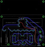
After some more measuring it appears that a board sitting on the 3mm supports molded into the Hammond 1598 case under Victor's board will clear the bottom of the board. Even with the specified #6 x 1/4 screws through the board there should still be 2mm clearance between the bottom of one of Victor's boards and the screw head.
So I've expanded the power supply board to the full 143.58 mm x 148.54 size of the 1598 case to take advantage of those two additional screw-in supports on the bottom of the case, for a total of 4 now. Much more solid than the power supply board just screwed into the two supports previously. No traces will be on the section under Victor's boards. For stand-alone caseless board use the new section can just be cut off with Dremel. I've put a dashed line on the top silkscreen as a cutting guide. I've also added extra 4mm holes so support standoffs can be used either with the full board or the shorter cut board. The cost difference between the 15cm x 15cm process at Seeed Studio (and probably other fab outfits) and the 10cm x 15cm isn't much, an extra dollar or two per board.
With the power board run out to the front panel like this there might be something else useful that could be added to the front panel, a LED or something.
The two files below are the same - one is just a png while the other is pdf.
Attachments
Last edited:
- Status
- Not open for further replies.
- Home
- Design & Build
- Equipment & Tools
- A case and power supply for Victor's low THD oscillators