Thank you. An amazing post, however, the author seems to concentrate on high power Germanium transistors only.
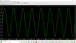
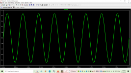
Example of 20kHz crossover distortion.
See attached image.
I do not know. The only thing I know is 20KHz is a very low frequency for almost anything not mechanical. I say this, not because of your post ( as I said : I don't know ), but, because, there are some people in this forum who really think 20KHz is a high frequency. Strange. 20KHz is nothing even for modern tubes.
See attached image.
Attachments
Yep
That is the only problem, crossover distortion at high frequency.
LM7171 is a beautiful opamp. slew rate is ridiculous fast.
So it is a prime candidate to make a no bias amplifier work.
Of all the crazy ideas I have thought up.
It is what I originally became so attracted to the 7171
super fast slew rate.
Building various no bias amps directly driven by op amps in my younger years.
Most sounded ok, but had a distinct crackle at high frequency.
I realized not knowing much...lol that faster opamps reduced the effect.
Then again I have simulated/ not built no bias amps with .006 distortion at 20 kHz
using a LM7171.
Last edited:
The 7171 has a large output capacity for an op.amp and the output impedance is low which is helpful in terms of switching a transistor off.
For more info on this see https://keith-snook.info/wireless-w...970/Class Distinction in Audio Amplifiers.pdf - particularly the passage on Hole-storage phenomena.
There is a bit more information re this on Bob Cordell's website.
It would appear the current capacity of 7171 is not enough to deal with stored charge issues quickly enough at 20kHz - frequency having an inverse relationship with time.
I have mentioned to all and have published many threads on the topic.
There are many ways to reduce the 0V distortion, even, with the direct approach.
LM7171 and LM6171 are only two of the solutions. There are many.
LM6171 has a slew rate of 350 V / us and LM7171 has a slew rate of around 500 V / us at a voltage difference of nearly 0V between the positive and negative inputs of the amplifier.
350 V / us will jump 0.7V in 2ns. This is two nanoseconds. This is at 0pF output capacitance. Most low power transistors have <= 5pF. This should not be a problem for the amplifier.
Higher power transistors have higher parasitic capacitances. This is why ( and for many other reasons ) only Toshiba transistors must be used for any audio.
However, the problem is NOT, I repeat, NOT, the 0V distortion. The problem is the machine gun noise which happens when the transistor is switched very quickly.
I am not sure whether I am the only one who gets this noise or this is a general problem. I have tried a few, different amplifiers and many transistors, some of them, ultra high frequency transistors.
The higher the current, the higher the frequency of the machine gun bangs.
These bangs are not like popcorn. They are very loud.
Spice will not help you. Use a perforated board and make one to find out.
In this sense, a way to slow down the transistors in the direct schematics in order to avoid the machine gun noise ( banging a few bangs a second, the higher the current, the higher the frequency of bangs ) may be to introduce Cbe. Cbe puts high impedance at low frequencies and low impedance at high frequencies. There may be some jumps up and down of Ua, when around 0V, but, the current is not wasted and goes through the load.
Please, see the attached.
Please, see the attached.
Attachments
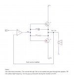
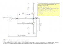
Another point is I have not used emitter resistors. Thus, while one of the transistors open and the other one closes, because they are slow, there may be a point where the two transistors are, to an extent, open and, thus, switching current would flow from Vcc to Vee.
Therefore, a good way would be to investigate whether emitter resistors would eliminate the machine gun noise.
Although, I do not have an oscilloscope, I intend to make a test circuit and test the ideas to see what helps and what not.
A good idea may be to install only one of the transistors and see whether I still get the machine gun noise. The other transistor can be replaced with a resistor or not installed at all. Not a good test, but, may reveal something.


No coils and transformers. They are noisy.
There may be a possibility for a base coil to limit huge frequencies, instead of the capacitor. Again, this will make electromagnetic and magnetic noise. Must be toroidal, yet, they decrease and do not eliminate the noise. Can be encased too.
As discussed in threads, which, I have specifically made for the direct schematic, LM6171 and LM7171 have a current limiting circuit at the output.
Thus, at 0V, during the switch, the amplifier current maximum value must not exceed the rating, so, the protection is not switched on to make bangs and noises.
Thus, at 0V, during the switch, the amplifier current maximum value must not exceed the rating, so, the protection is not switched on to make bangs and noises.
Interesting posts! Please, post more!
Machine Gun Noise :
I have done some additional investigation, as, previously, mentioned. I will publish an additional document. For now :
The direct circuit works OK in mono! No machine gun noise. Rbe improves the sound. The machine gun noise is present in stereo. Most likely, the reason is fast switching with high current, which, loads the power supply and capacitors and, occasionally, proliferates from one channel to the other.
The direct push pull circuit and the machine gun noise have been investigated. The circuit has been made to work. A document, called " Machine Gun.doc ", has been published. Please, scroll down to the " Addendum " and read a page and a half only, except when interested in more information : https://drive.google.com/drive/folders/19EGkuJHapxfTlS9T0iIIMLXz-E-U9-1r
More test revealed the great importance of all resistors, Rbe, Rce and Rcb around the secondary transistors. The lower the values the better. Another desired schematics, showing this approach has been added as Figure 23. towards the end of the document.The direct push pull circuit and the machine gun noise have been investigated. The circuit has been made to work. A document, called " Machine Gun.doc ", has been published. Please, scroll down to the " Addendum " and read a page and a half only, except when interested in more information : https://drive.google.com/drive/folders/19EGkuJHapxfTlS9T0iIIMLXz-E-U9-1r
I have been through hell and back, fighting with Sziklais, with or without offset.
I have tested the idea of providing offset with resistors. The simple, direct circuit has been tested as well as a circuit with Sziklais. A Darlington is to be tested and the document updated. The Darlington will be tested when only the primary transistor is open at 0V and when the two transistors are open.
The document is called " Offset with Resistors.doc ", which, is here : https://drive.google.com/drive/folders/1I-gJFsjT1I2w7QNfagujAo1DXqRQrGxG
Scroll towards the bottom for schematics and conclusions.
I have found I have no way to trust Spice THD calculations as by varying the step, I can get it to be anything. from 3% to .000014 for the same schematic. There is something fundamental I do not understand about the .four parameters.Effect of an pamps first pole on unbiased Class-B jump distortion
Hi Steve,
Continuing simulations with no bias and a fast opamp. This post is with an output pole in my opamp model closer to the LM7171 first pole.
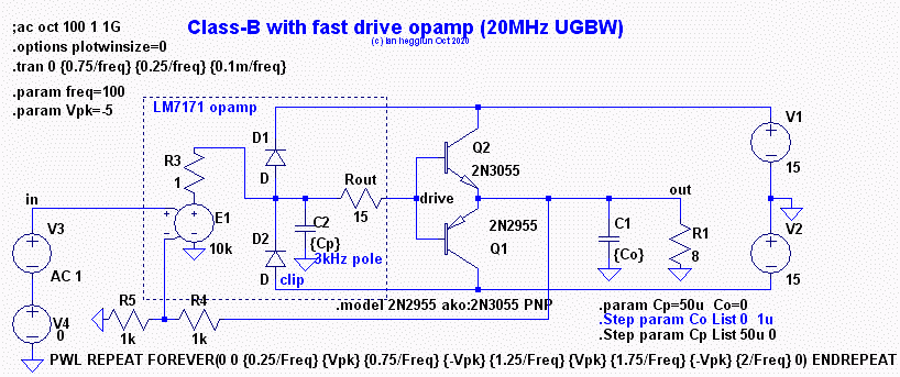
The pole capacitor was set for 3kHz using an AC run with R4 removed (open-loop). With Avol of 80dB the unity gain frequency for this model is found to be 20MHz. The value of Cp can be stepped so the effect of this pole can be seen on plots (below) for a 5V input 100Hz triangle wave of 100Hz:
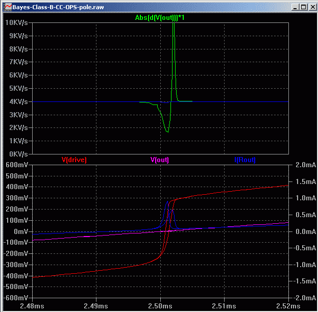
The top pane is the gm variation in the crossover region: Blue is without the pole and Green is with 20MHz GBW.
Lower pane shows the base drive voltage moving through the "jump" region and the drive current. BTW The transistor capacitance in this region is the drive current divided by the slope of the drive voltage, it appears to be around 2nF. The opamp pole lengthens the transition and reduces the slope (less drive current flows).
Now the effect of the opamp pole on distortion readings with 5Vpk input, 100Hz, sine (below)

The upper pane shows the output voltage in the crossover region, Green with the pole.
The lower pane shows the output voltage of the weighting filer which boosts the higher harmonics like our ear. Green is with the pole, delayed and slightly larger but not by much.
The weighted THD and unweighted readings with the pole are below:
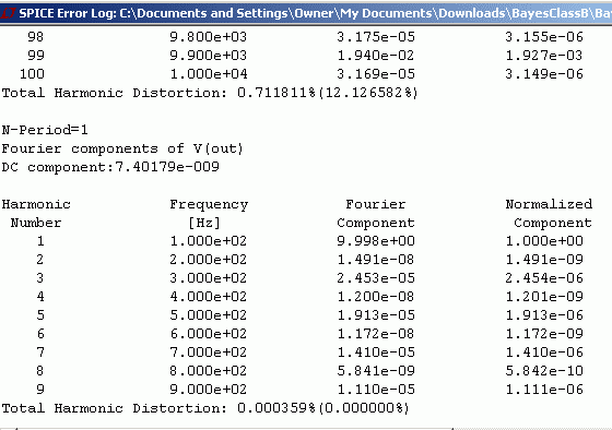
.
And with no pole the values are almost identical:

.
The weighted distortion, if it can be believed, suggests the huge gain variations when the pole is added (seen in the first triangle wave plots) hardly affects what we would hear as crossover distortion when no bias is used with a fast opamp. Listener tests are need to verify this, preferably using bench tests.
The simulated distortion test circuit is also included in the attached zip for a short clean guitar strum for those interested if the crossover distortion is audible with music and what type of music makes it most noticeable.
Lastly, adding output capacitance causes oscillation when the series resistance (ESR) is less than 0.3 ohms and Co is more than 200nF with this model. With a 1uF output capacitor the series resistance needs to be more than 0.5 ohms to stop oscillation with this model. The frequency of oscillation was around 500kHz.
Yea, load parameters can play hell on stability.
I have updated the document. A Zobel network did help and was found to be sufficient, yet, the other resistors can still be used with high values. The document was updated with the Zobel network and some mistakes on one of the last schematics have been corrected.
The Zobel network was used with Sziklais only. No need to use such without, but, whoever wants can.
I use the Zobel network to, even more surely, prevent Sziklai oscillations. Other uses are to cancel the parasitic inductance of the speaker.
The Zobel network was used with Sziklais only. No need to use such without, but, whoever wants can.
I use the Zobel network to, even more surely, prevent Sziklai oscillations. Other uses are to cancel the parasitic inductance of the speaker.
- Home
- Amplifiers
- Solid State
- A Buffer for Class AB Amplifiers