I never did post that. I'll attach them here and I do have one question about them.
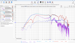
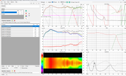
So I have here the woofer near field, the port near field, and their aligned sum.
Also, in red (SPL not aligned so ignore the fact that its much lower) is the woofer far field measurement.
Why is it that the aligned sum does not match closely the far field measurement of the aligned sum here?
When I did my 3 way the far field pretty well matched the aligned sum. Here, it does not.
Near fields gated at 1000ms, far field gated at 38.1ms. I take these in my shop which is very big with high ceilings so that's why there isn't a ton of reflections even gated that far out.
Attachments
I'm not certain, but the first thing I'd say is that 38ms is a large gate. How far are the closest walls/floor from your mic line of sight, and how far is the mic from the speaker?
It's a 17 foot ceiling and the back wall is probably 50 feet away. The side walls are probably 30 feet either side. It's big. It's an old industrial print shop turned into an electrical engineering prototyping shop.
Mic is 36" from the driver. Near field it's 5mm from the driver
Mic is 36" from the driver. Near field it's 5mm from the driver

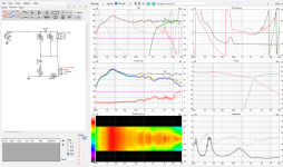
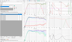
k, I think I'm done now. This tweeter really sucks. See "sad face" around the horrendous distorion.
I took huge pains to cross this thing as steeply as possible without adding a million components in. Even a small amount of SPL from the tweeter beyond 1k would distort the mid range. I guess it would be useful if you had an active crossover but with passive.... this tweeter is not the move.
3.2 minimum impendence but a total system nominal impendence above 4 ohm.
I have learned how important it is to choose your drivers wisely rather than making do with leftover speakers. I managed to squeak by with this one.
Attachments


I did attempt to wrap the enclosure in alcantara fabric. It did not work. We had nothing sharp enough to cut a straight line through it. It is VERY tough material. Even a scalpel would not work.
I have since bonded the 3d printed baffle to the wood face, bondoed the entire thing, and sanded it. I will hit with sandable primer, sand again, paint it, sand again, and hit with a 2k clear coat. It will be very shiny.
I have since bonded the 3d printed baffle to the wood face, bondoed the entire thing, and sanded it. I will hit with sandable primer, sand again, paint it, sand again, and hit with a 2k clear coat. It will be very shiny.
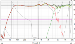
It looks like you haven't applied simulated baffle diffraction. Vituix can do this and then you won't have a measurement that looks like it was made by stereophile.Why is it that the aligned sum does not match closely the far field measurement of the aligned sum here?
The crossover design and not supressing the woofer breakup is hurting what could be achieved with those parts.This tweeter really sucks.
The crossover design is impeded by the impendence. If I want it to be used by the average 4 ohm amplifier then it is this. I can, and have, made other XO designs. The caveat with those is a lower impendence or padding the entire thing with resistors to get the impendence up.
The baffle diffraction is applied in the crossover range with the far field measurements. I do not care to bother with applying it below 400 Hz using the merge tool since what happens below 400 Hz I cannot affect at this stage in the design. Were it a 3 way, I would apply it. Since it is a 2 way with an xo around 3500 Hz, there really is no point. The baffle is taken into account with the far field measurements.
The baffle diffraction is applied in the crossover range with the far field measurements. I do not care to bother with applying it below 400 Hz using the merge tool since what happens below 400 Hz I cannot affect at this stage in the design. Were it a 3 way, I would apply it. Since it is a 2 way with an xo around 3500 Hz, there really is no point. The baffle is taken into account with the far field measurements.
Here is a steeper woofer side
This build is coming to an end. All I have left is paint and XO assembly when the components come in.
Series crossover's are a little annoying but I finally got the hang of it. I wouldn't shy away from a series in the future. Once you kind of understand what each component is doing in the network it starts to become easier.
This, of course, was exacerbated by me wanting steep slopes so I had to go to a 3rd order series. I wouldn't want to mess with a 4th order....
I think the main advantage of a series crossover is you really don't need much resistor action. You can pad down either driver just using the filter. If you do need a resistor they end up being quite small and dissipating small amounts of wattage.
I'm all in around $150 for the pair
XO- $45
Woofers- $72
Tweeters - $36
Wood - Free, leftover from building a crate
Paint - Leftover stuff I had on my shelf
Will post up pics when they are done.
Attachments
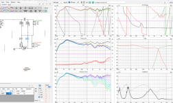
A good crossover will equalize the overall frequency response of the speaker at the same time as transitioning the drivers to each other. Not properly compensating the baffle step is a common reason for a DIY speaker sounding thin unless the plan is to listen to it close to a wall or corner.The baffle diffraction is applied in the crossover range with the far field measurements. I do not care to bother with applying it below 400 Hz using the merge tool since what happens below 400 Hz I cannot affect at this stage in the design. Were it a 3 way, I would apply it. Since it is a 2 way with an xo around 3500 Hz, there really is no point. The baffle is taken into account with the far field measurements.
You have gone to a reasonable amount of trouble in making some off axis measurements, avoiding a few minutes in the simulation program to get a more accurate view of what you have to start with is an odd choice to me.
Resistors of decent quality are relatively cheap to buy and in more conventional topologies they can be quite helpful in allowing the overall frequency balance to be adjusted.
Fluid,
I applied it and it made no difference. This baffle also has an extreme roundover which you'll see when I'm done.
I applied it and it made no difference. This baffle also has an extreme roundover which you'll see when I'm done.
In a finite baffle of any shape there has to be diffraction loss, your graphs don't look right to me in that regard, there are a few ways things can go wrong in the making and combining of measurements for simulating crossovers that make similar looking graphs. It is of course possible to intentionally create that sort of bump like Wilson's TuneTotI applied it and it made no difference. This baffle also has an extreme roundover which you'll see when I'm done.
Fluid,
I think the reason it doesn't make any difference is because I am only applying the diffraction below 400 Hz. I am merging my far and near field measurements at 400 Hz.
The far field already has it applied since it'd a real world measurement. The lower frequency portion comes from the near field which doest have baffle applied. So applying simulation baffle effects only does anything below 400hz
Here is them next to eachother. You can see applying baffle step to the lower frequency makes no difference. It is 1 db higher because the merger tool isn't perfectly accurate. None of this is perfectly accurate, it is a simulation
Attachments
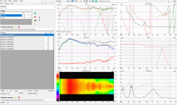
I took a longer look back through the thread to try and understand what might be going on. In post #121 above the far field response looks to have the expected diffraction loss of about 6dB from the level at 1K vs 150 to 200Hz. The nearfield of the woofer also looks as expected from the box and port models early on. The port output is what looks a little odd, there is a quite broad output either side of the tuning frequency, the level of the port at 15Hz is about 10 or more dB above the woofer. This is where they should be converging to be the same. It looks like the port and woofer have been combined without the port output being scaled relative to the area of the woofer. I don't know if you combined them in REW or the merger in Vituix.Here is them next to eachother. You can see applying baffle step to the lower frequency makes no difference. It is 1 db higher because the merger tool isn't perfectly accurate. None of this is perfectly accurate, it is a simulation
This image from the merger section of the Vituixcad manual is a good example of what I would expect. A more triangular port output somewhat below the level of the nearfield woofer converging at about 15Hz and the bass being lower than the midrange when diffraction simulation is added. Doing all the merging in Vituix and using the Force to gradient option lets you see if the combination makes sense.
The port design from earlier is not intended to be a boombox so I suspect scaling and diffraction applied in the Vituix merge tool will help to get it looking more realistic.
Fluid,
I did cut a corner and aligned the sum in REW. I found this works for the assembling everything above 400 hz.
I went ahead a aligned the sum, applying the baffle step to the low end properly with the Sd of the woofer and the port respectively.
This should be what it looks like, same conclusion as you almost.
It did not affect anything near the XO point so I think cutting the corner was acceptable. VituixCad is basically a mirror image of the WinISD sim. This is a good sign for the system.
One question though: why did you set Sd of the silver flute to 75? On madisound it has the 6.5" as 132. The port is 2" in diameter and by my calculation that comes out 20 cm2. Am I using the wrong calculation here?
Also, I really hope this sim ends up being correct because this graph looks great for $150 system.
All that is left is paint and assembling the XO when the parts come in. Hopefully it all gets done before I head out racing for the weekend and I can get the measurement of the system taken to share with everyone.
Attachments
Fluid,
I don't really understand why VituixCAD doesn't show the full output of the port. In REW you can clearly see the response hangs on way parts what VCAD shows. That port hits down to 30 hz. VCAD shows a roll off starting at around 70 hz.
I suppose we will find out soon enough when I take the measurement of the full system.
I honestly don't have huge faith in the merger tool showing the low end. Then again, I feel like I should be seeing the port measurement leak further into the far field measurement. I saw that with my last 3 way build but I do not see it here. Maybe I am missing something.
Attachments

Did you ever post the separate files for woofer farfield, woofer nearfield, port nearfield?
VituixCAD, including the merger tool, is very accurate if you give it very accurate inputs. I have had several times where the measurements of my prototype xo did not match what the VituixCAD simulation had predicted. In all cases I later was able to determine what my user-error was. Here is a great example, where the simulation is within less than a dB from the final measured speaker from 20Hz to 20Khz.
VituixCAD, including the merger tool, is very accurate if you give it very accurate inputs. I have had several times where the measurements of my prototype xo did not match what the VituixCAD simulation had predicted. In all cases I later was able to determine what my user-error was. Here is a great example, where the simulation is within less than a dB from the final measured speaker from 20Hz to 20Khz.
- Home
- Loudspeakers
- Multi-Way
- A boring 2 way build