The penny pinching part of my brain can't help wondering whether we need Satori quality for large woofer drivers in a 3-way. Would the SB23NRX, SB23NBAC, SB23CACS, etc be any worse for these roles?Hi..
Yes. From the simulations that fluid did, we came to the conclusion that having 2 Satori WO24Ps per speaker was better in terms of directivity and other aspects.

Hi tcpip,The penny pinching part of my brain can't help wondering whether we need Satori quality for large woofer drivers in a 3-way. Would the SB23NRX, SB23NBAC, SB23CACS, etc be any worse for these roles?
From whatever I know, the drivers you suggested would work well in this specific 3 way project.. 😀 and all drivers would have fit into a more svelte cabinet given the drivers I have for mid and tweeter. 🙂
Originally, I got a pair of Satori drivers at a price which I couldn't refuse at the time. So it made no sense to buy the SB23 drivers comparing the marginal price difference (at that time).
From the simulations that fluid did for me, I think the conclusion was that for a woofer of this size on a cabinet of the dimensions I chose, two woofers gave better directivity compared to one woofer. It had nothing to do with the needing two Satori woofer drivers per speaker. In fact I could have gone with a Satori mid like MR16P if I had known that I would eventually chose 2 of these woofers. 🙂
But due to the break I had between the last simulations fluid did and now, I have been learning more and thinking of all sorts of possibilities with a bass module having two drivers. I have become quite interested in modular speaker projects.
For this purpose, I think a twin Satori bass module which can be run even upto 1kHz will be a good base. In fact In addition to a top module that looks similar to what I have already mocked up earlier using xps foam, there is this Directiva R2 top (mid+tweeter) that I can use with such a bass module with lower frequency crossover: https://audiosciencereview.com/foru...e-platform-speaker-project.20407/post-1043389
There is the possibility of doing something that looks like this: https://www.audiovero.de/en/horn-loudspeaker.html with a higher crossover point and with a CD+ (experimental) horn handling the higher frequencies (even though it may need significant padding down of levels of the upper module). One more thing I want to try in the distant future along with such a bass module is a coaxial top with the top module resembling the top module (but with a readily available coaxial driver) here: http://www.5een.co.uk/FSTNT1.htm
😀
There is always the question of why would I need so many speakers. 😀 For that one I have no answer.. 😀
Regards
Vineeth
Last edited:
Seeing all the xps foam experiments going on and impatient with the delay in box building for the project, I made a 51L sort of braced, sealed box out of left over foam, filled it generously with some polyfill and placed a Satori WO24P woofer in it. 😀

There might be tons of resonance issues etc. Still I took a nearfield measurement and got the below response (1/6 octave smoothed) 😀

With no expectations, I made some basic filters on EQ APO as below and applied it to the woofer

Then I played some songs.. Straightaway, I liked it. It is a fun driver.. 😀 It has good bass. I never expected good midrange from it. But it does well in that part too.. All this in a foam box.. Now I am impatient to see 4 of these in action along with proper mids and tweeter in a proper cabinet.. 😀
And I found out I like sealed boxes.
Even more fun is hearing the DSP live in action. I can make changes in EQApo on the fly and listen to the changes.. 😀
There might be tons of resonance issues etc. Still I took a nearfield measurement and got the below response (1/6 octave smoothed) 😀
With no expectations, I made some basic filters on EQ APO as below and applied it to the woofer
Then I played some songs.. Straightaway, I liked it. It is a fun driver.. 😀 It has good bass. I never expected good midrange from it. But it does well in that part too.. All this in a foam box.. Now I am impatient to see 4 of these in action along with proper mids and tweeter in a proper cabinet.. 😀
And I found out I like sealed boxes.
Even more fun is hearing the DSP live in action. I can make changes in EQApo on the fly and listen to the changes.. 😀
Last edited:
That is a nice bass response. From the look of your plot it seems that F3 is at 40 Hz and F10 is at 25 Hz.
The XPS foam is a fabulous material for doing mock-ups and experiments. It helped me work out some details when doing my last project. I think xrk971 was the first to bring this idea to our attention.
j.
The XPS foam is a fabulous material for doing mock-ups and experiments. It helped me work out some details when doing my last project. I think xrk971 was the first to bring this idea to our attention.
j.
Attachments
Thank you. 🙂That is a nice bass response. From the look of your plot it seems that F3 is at 40 Hz and F10 is at 25 Hz.
The XPS foam is a fabulous material for doing mock-ups and experiments. It helped me work out some details when doing my last project. I think xrk971 was the first to bring this idea to our attention.
j.
In fact it is your recent experiments with foam that motivated me to take up xps foam again. 🙂
(By the way, the texteme mid + Satori tweeter combination looks really good in the pic. SB texteme drivers are not available in my country yet)
The first time, I came across this foam material was when xrk started using it some years back. Back then , I had tried a few of his projects using the peerless tc9fd18 driver. It was really fun.
You are spot on regarding the bass response specs 🙂
Here is the impedance plot of the driver in the box (The magnitude peak looks to be exactly at 40Hz along with the zero crossing of phase):
I can see some blips in the plot above, probably resonances at the lower frequencies along with that driver's inherent blip around 1kHz. I was lazy to not do anything more to the foam box in trying to treat the resonance problem.
Hopefully I will get the real boxes soon. 🙂
Regards
Vineeth
Some more experiments with WO24P and SB Audience Rosso65CDN-T on Faital Pro LTH142 horn
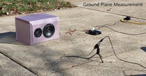
Still, waiting for the final boxes. In the meanwhile, to study taking more polar measurements and familiarize more with VituixCAD FIR filter generation capability, I tried to do polar measurements for a speaker set up like below 😀

Measurement in Progress:

Driver WO24P-8 horizontal polar:

Rosso 65CDN-T horizontal polar:

Rosso 65CDN-T vertical polar:

Sample VituixCAD FIR crossover:

EQ Apo filter implementation:

As the next exercise, I am planning to study implementing an IIR crossover 😀 😀
The idea behind all this was to learn how a readily available horn will sound like before proceeding with customised/more complicated horns in addition to killing some free time 🙂
Thanks & Regards
Vineeth
Still, waiting for the final boxes. In the meanwhile, to study taking more polar measurements and familiarize more with VituixCAD FIR filter generation capability, I tried to do polar measurements for a speaker set up like below 😀
Measurement in Progress:
Driver WO24P-8 horizontal polar:
Rosso 65CDN-T horizontal polar:
Rosso 65CDN-T vertical polar:
Sample VituixCAD FIR crossover:
EQ Apo filter implementation:
As the next exercise, I am planning to study implementing an IIR crossover 😀 😀
The idea behind all this was to learn how a readily available horn will sound like before proceeding with customised/more complicated horns in addition to killing some free time 🙂
Thanks & Regards
Vineeth
Last edited:
Two points to mention. It may be the picture but it is important for the front of the baffle to be over the centre of the turntable so that the point of rotation is consistent. If it isn't the polars won't be as accurate.
The baffle shape is contributing a lot of gain at 500Hz. Probably because the height is about twice the width. This may just be an experiment and not what you actually end up using but something to think about. Power response peaks are not ideal, you may prefer the sound with an on axis dip to balance the off axis gain. Easy enough to try with a PEQ band.
The baffle shape is contributing a lot of gain at 500Hz. Probably because the height is about twice the width. This may just be an experiment and not what you actually end up using but something to think about. Power response peaks are not ideal, you may prefer the sound with an on axis dip to balance the off axis gain. Easy enough to try with a PEQ band.
It's not so clear cut as this, especially where power is concerned, if all else is done properly.the front of the baffle
Vague, caveated and providing no real information, what is the point of such posts?It's not so clear cut as this, especially where power is concerned, if all else is done properly.
My understanding is that the center of rotation (the axis of rotation) must be aligned with the front of the baffle. If this is done, the distance from the mic to the device under test will stay constant as the device is rotated. This preserves the phase consistency between all the polar measurements, and it maintains the correct SPL magnitude relationships.
I have never gotten it perfect, because the time-wise location of the impulse peak varies by about 1 microseconds from 0 to 90 degrees... the equivalent of about 3 mm.
Allen - can you expand a bit on what you are getting at?
I have never gotten it perfect, because the time-wise location of the impulse peak varies by about 1 microseconds from 0 to 90 degrees... the equivalent of about 3 mm.
Allen - can you expand a bit on what you are getting at?
Thanks a lot fluid for these suggestions 🙂Two points to mention. It may be the picture but it is important for the front of the baffle to be over the centre of the turntable so that the point of rotation is consistent. If it isn't the polars won't be as accurate.
The baffle shape is contributing a lot of gain at 500Hz. Probably because the height is about twice the width. This may just be an experiment and not what you actually end up using but something to think about. Power response peaks are not ideal, you may prefer the sound with an on axis dip to balance the off axis gain. Easy enough to try with a PEQ band.
I too read about the baffle being the center of rotation in the Vituix instruction manual.
This was an attempt to test if I could do it with the small rotating turntable I had.
I also wanted to take horizontal and vertical polars from 0 to 180 degrees to understand the sort of manual effort required.
In fact I went upto 130 degrees in the horizontal plane and got measurements like this for WO24P
In the above plot I saw some weird observations like the rise in amplitude of the 100 degree measurement compared to 90 degree measurements and its sort of "mis-alignment" along the frequency axis compared to other angles below it/above it. I am thinking that the distance issue or some other measurement issue screwed it up given that I had not done anything like raising the level of amplifier etc. Eventually I gave up and took only upto 90 degrees.
From this exercise, I also think that I need a bigger radius turntable with some heavy duty rotating mechanism if I am going to measure a heavy floor standing box. This small radius plastic one in the pic will handle even my own weight if I distribute my weight uniformly on top of it but it will topple over if I put a heavy box with its baffle at the centre of the disc.
I tried my best to put the baffle aligned to the centre point of the rotating disc while also raising the height of the driver to about the center of the room.
But I think in the end the best I could manage was within a 2-3cm offset of the baffle surface from the center towards the front. So as you rightly suggested, this set of measurements will have errors.
This foam box is not much close to the dimensions of the final box. Final box (for the Satori woofers alone) will be about 30ish cm in width with 2.5cm edge rounding and about 88cm ish height along with around 35ish cm depth. It will have two 35ish liter internal partitions, one for each Satori woofer. (My ideas about a tear-drop ish shaped rockport-type box was turned down by the manufacturer of the box due to material, cost and effort-related concerns. Since I thought something is better than nothing, I accepted the his proposal of the below type box) 🙂 The separate top module will have the chamfered type box with the 5inch SB CAC midrange and SB26CAC tweeter in a waveguide.
In this present foam box, the baffle width was 354 mm and height was 600 mm. The full FIR filter-based crossover was done by VituixCAD with focus on flatness of ON-axis response. I will also try an FIR with focus on listening window flatness and then a regular IIR one where we manually do the driver passband linearization and decide the crossover filter topology considering "z-offset" of drivers etc. Also this CD+ (another horn) is for the 15PR400 in a triangular shaped box (similar to the one in your 2 way project pic with Yuichi type horn). This experiment I just put together for studying all the above aspects.. 🙂
Will update more about this in coming days.. 🙂
Regards
Vineeth
Last edited:
You are welcome, the CTA2034 standard allows for up to 5cm variation in the rotation axis, so I doubt that your results are completely off at 2cm or so, just something to think on if you upgrade the rotation table.Thanks a lot fluid for these suggestions 🙂
There could be a setup issue but the off axis does not always fall monotonously with further angles, you can get a bounce back like that.In the above plot I saw some weird observations like the rise in amplitude of the 100 degree measurement compared to 90 degree measurements and its sort of "mis-alignment" along the frequency axis compared to other angles below it/above it. I am thinking that the distance issue or some other measurement issue screwed it up given that I had not done anything like raising the level of amplifier etc. Eventually I gave up and took only upto 90 degrees.
This seems well thought out to me from ASR member 617From this exercise, I also think that I need a bigger radius turntable with some heavy duty rotating mechanism if I am going to measure a heavy floor standing box.
http://nicholasmart.in/measurement_platform/
That looks like it will work out well, and certainly better than nothing 🙂(My ideas about a tear-drop ish shaped rockport-type box was turned down by the manufacturer of the box due to material, cost and effort-related concerns. Since I thought something is better than nothing, I accepted the his proposal of the below type box) 🙂
This is really nice to know. I never knew that there is this much margin for error.. 🙂You are welcome, the CTA2034 standard allows for up to 5cm variation in the rotation axis, so I doubt that your results are completely off at 2cm or so, just something to think on if you upgrade the rotation table.
This I am hearing for the first time and is very interesting..There could be a setup issue but the off axis does not always fall monotonously with further angles, you can get a bounce back like that.
I almost concluded that it is a surely a measurement issue.
What is a bounce back? Can you explain a little more about how this happens?
Awesome.. seems doable. I will enquire about the local manufacturability of the base part of this turntable setup. Cant accommodate the ladder type thing attached to it at home. Maybe I can improvise a little bit on the speaker-raising structure.This seems well thought out to me from ASR member 617
http://nicholasmart.in/measurement_platform/
I will try .. 🙂
Thanks you.That looks like it will work out well, and certainly better than nothing 🙂
I really hope that it will turn out into something nice, at least to my ears once everything is assembled 🙂
That a further off axis measurement can be higher in level at some or many points than one with a lesser angle, the response bounces back up.What is a bounce back? Can you explain a little more about how this happens?
Here is a quick example, have a look at the 150 degree response how it is higher than some others with lesser angles in the 800 to 1.8K range, 130 degrees does the same lower down. There is a similar thing in the green traces around 500Hz.
They should all join back together at lower frequencies when the cabinet dimensions have finished affecting the response, that is cut off in your measurement to know if it also follows that trend.
Yes, something that appears to make sense and is obviously a good place to use by default. However power doesn't have a phase component. Also, a speaker doesn't necessarily have a fixed origin. Still, with enough measurements we get the whole picture.This preserves the phase consistency
As the person who made the claim, the onus is on you to back it up.and providing no real information,
It wasn't a claim just an observation, one that was unnecessarily salty I'll grant you.As the person who made the claim, the onus is on you to back it up.
Vineeth, please check timing of gating in your measurements! Single channel measurement in REW sets t=0 automatically at highest amplitude, which might be reflected and some ms late from direct sound. This gives strange looking response just like we see in post #311 and 314.
Open impulse page of eg. 150deg measurement and you see red line showing gated window. If there is lower amplitude signal earlier, grab t symbol and move it left to onset of earlier peak.
I learned this wih my dipole indoor measurements, typically at 70-110 deg.
Open impulse page of eg. 150deg measurement and you see red line showing gated window. If there is lower amplitude signal earlier, grab t symbol and move it left to onset of earlier peak.
I learned this wih my dipole indoor measurements, typically at 70-110 deg.
Hi Juhazi,Vineeth, please check timing of gating in your measurements! Single channel measurement in REW sets t=0 automatically at highest amplitude, which might be reflected and some ms late from direct sound. This gives strange looking response just like we see in post #311 and 314.
Open impulse page of eg. 150deg measurement and you see red line showing gated window. If there is lower amplitude signal earlier, grab t symbol and move it left to onset of earlier peak.
I learned this wih my dipole indoor measurements, typically at 70-110 deg.
Thanks for this suggestion. 🙂
In fact I was surprised at the initial set of gated measurements I got because of the weird behavior after about 60 degrees precisely because of the problem you mentioned. REW somehow took the peak of the delayed replica of the impulse, set the reference there and took the window around it. But afterwards, I went and moved the window reference times to zero for all angular measurements.
Eg: the zero degree measurement looks like this:
The 80degree measurement looks like this:
Initially, the reference timing was set by REW somewhere else around 8ms.
I adjusted the window to get the Ref time = 0
The 120 degree measurement looks like this:
Looks like something really went wrong with the 80degree measurement due to how the impulse response looks.
On top of that REW kept freezing multiple times in between and I had to take measurements at some angles thrice or more.
Really makes me think If it is better to use ARTA as the measurement software.
I also have some doubts about the capability of the Dayton EMM-6 measuring mic..
Took another shot at IIR filters-based crossover.. Don't know how much good it is:


Earlier FIR filter-based crossover for comparison:

Thanks
Vineeth
Earlier FIR filter-based crossover for comparison:
Thanks
Vineeth
- Home
- Loudspeakers
- Multi-Way
- A 3 way design study