I don't see any problems of the gate being too short. I keep the mic at one metre, and the gating I get is between 4msec and 5msec, which gives me farfield SPL which, according to ARTA, is valid down to somewhere between 200Hz and 300Hz. If I need accurate SPL data below about 500Hz (which we all need for 3-way designing) then we need to merge nearfield SPL with gated farfield. So, I'm not seeing the issue here. Use your 4.5msec gating and it'll work just fine.The blue wand is actually a PVC pipe. I think I asked the shopkeeper for a 1m long 3/4 inch diameter PVC pipe. I expected a white colored one but unfortunately they had only these blue colored pipe in stock. so I bought it.. 🙂
Thanks for the suggestion. I agree. But shortening of the gate also reduces the frequency resolution we have at the lower frequencies with gated farfield measurements like these, especially below 1kHz. For the mid-tweeter crossover above 2k, it may have less impact but as augerpro pointed out earlier 6-7ms or more for gate seems to be a reasonable gate window. This is my next target. 🙂
For measurement, I explored and found out that my apartment has a big open area on the roof. It means I would have to move a heavy speaker to the roof and then raise it about 1.5 to 2m above the ground. But I will try and see if it works.. 😀
I don't see any problems of the gate being too short. I keep the mic at one metre, and the gating I get is between 4msec and 5msec, which gives me farfield SPL which, according to ARTA, is valid down to somewhere between 200Hz and 300Hz. If I need accurate SPL data below about 500Hz (which we all need for 3-way designing) then we need to merge nearfield SPL with gated farfield. So, I'm not seeing the issue here. Use your 4.5msec gating and it'll work just fine.
Thank you. I will definitely try out the 4.5ms in-room gate time first once I get the speaker cabinet made hopefully in the near future.. 🙂
My thinking about needing more resolution was this: 4.5ms gate means the frequency resolution we have is 1/4.5ms = 222.22 Hz. So we are talking about binning the entire frequency range into frequency buckets of width = 222.22Hz.
This means I have about max. four or five data points below 1K. So higher Q resonances etc, if they exist, it might not be visible (but now I agree that, to see such things captured in the measurement, we may need an alternate measurement method or much higher gate width and may not be worth pursuing). At higher frequencies, because of the logarithmic scale we use on the frequency axis, the frequency buckets will look closer together. But at low frequencies their width will make itself more visible. This could all be just because I am overthinking.. 😀
But as you said I will also try with merged nearfield+farfield.
Last edited:
I have tried, for instance, increasing the mic distance to 2m. For reasons I could not figure out, this didn't work. I got squiggles in the impulse graph far earlier than the first floor bounce. Shifting the mic to 1m took those early squiggles away.Thank you. I will definitely try out the 4.5ms in-room gate time first once I get the speaker cabinet made hopefully in the near future.. 🙂
My thinking about needing more resolution was this: 4.5ms gate means the frequency resolution we have is 1/4.5ms = 222.22 Hz. So we are talking about binning the entire frequency range into frequency buckets of width = 222.22Hz.
This means I have about max. four or five data points below 1K. So higher Q resonances etc, if they exist, it might not be visible (but now I agree that, to see such things captured in the measurement, we may need an alternate measurement method or much higher gate width and may not be worth pursuing). At higher frequencies, because of the logarithmic scale we use on the frequency axis, the frequency buckets will look closer together. But at low frequencies their width will make itself more visible. This could all be just because I am overthinking.. 😀
But as you said I will also try with merged nearfield+farfield.
In my living room, I have not been able to get clean SPL from gated MLS impulse data at distances greater than 1m. This seems to match some other speaker builders' experience. If you can beat it, that'll be great and I'll learn from you.
On the other hand, you have no alternative to the nearfield measurement and merging, when designing crossovers which operate in the '00s of Hz range. In other words, for 3-way and higher ways. So I suggest you don't try too hard to stretch your gated farfield to low frequencies, and do the nearfield and merge.
The problem is smoothing of the data. In this context valid does not mean accurate it means not total garbage, the longer the gate the better but the difference between 5ms and 6 or 7ms is not huge, it really needs to be 10ms or greater which becomes much more challenging.I don't see any problems of the gate being too short. I keep the mic at one metre, and the gating I get is between 4msec and 5msec, which gives me farfield SPL which, according to ARTA, is valid down to somewhere between 200Hz and 300Hz. If I need accurate SPL data below about 500Hz (which we all need for 3-way designing) then we need to merge nearfield SPL with gated farfield. So, I'm not seeing the issue here. Use your 4.5msec gating and it'll work just fine.
You can see in the Vituix Time Window Tool the frequency at which the data loses all validity where it is 1/1 octave smoothed and the frequencies where the smoothing is half an octave and one third of an octave.
This thread has a lot of good information on quasi anechoic measurements. The posts above and below this cover this issue.
How to make quasi-anechoic speaker measurements/spinoramas with REW and VituixCAD | Page 5 | Audio Science Review (ASR) Forum
Nearfield measurements are valid somewhere up to 300 or 400Hz so it is the range from there up to about 800Hz where there is a significant loss in measurement resolution with short gates. If the drivers are well behaved and the cabinet it good then there may well be no problem and nearfield polar measurements can be taken to check for issues, impedance measurements etc.
You are not overthinking it but don't let it stop you from trying things out, as long as you know the limits of the measurement technique there is less chance of making a bad choice because of it.This could all be just because I am overthinking.. 😀
But as you said I will also try with merged nearfield+farfield.
Merging measurements is a good technique but the above cautions should be considered.
Attachments
I have tried, for instance, increasing the mic distance to 2m. For reasons I could not figure out, this didn't work. I got squiggles in the impulse graph far earlier than the first floor bounce. Shifting the mic to 1m took those early squiggles away.
In my living room, I have not been able to get clean SPL from gated MLS impulse data at distances greater than 1m. This seems to match some other speaker builders' experience. If you can beat it, that'll be great and I'll learn from you.
On the other hand, you have no alternative to the nearfield measurement and merging, when designing crossovers which operate in the '00s of Hz range. In other words, for 3-way and higher ways. So I suggest you don't try too hard to stretch your gated farfield to low frequencies, and do the nearfield and merge.
Thank you. 🙂 I have been using REW till now for frequency response measurements. I think it uses a linear frequency sweep-based signal for frequency response measurement. I don't know how better would be the MLS based ARTA measurements in terms of SNRs obtained/frequency resolution obtained/noise+interference (from reflections) suppression because of my current lack of understanding about that software.
Regarding higher mic distances causing issues with squiggles, the following is my current understanding about it. In the ideal case, every squiggle after the main peaks of the driver/speaker response are contributed more by the reflections arriving at the mic compared to driver/speaker alone response. So it could be that some reflections from somewhere else in the room other than the floor is arriving before the floor reflection when distance from speaker to mic is increased. This is just my hypothesis from limited understanding🙂
I will definitely end up using merged gated farfield+scaled near field responses only in this project as it is one of the most practical ways available to DIYers so far. 🙂
However, if I was really into this measurement technique exploration, at least to get a reasonably accurate ON-axis response alone, I will definitely try these methods based on array beamforming techniques (at least to satisfy the curiosity about how good they are in practice.. 😀 )
1)(PDF) Enhancement of loudspeaker impulse response measurement using beamforming methods
2) (PDF) Quasi-Anechoic Measurement of Loudspeakers Using Adaptive Beamforming Method
I am not aware of any better methods due to the lack of my exposure to the literature available in this area.
Since we don't have Klippel or DIY versions of it, probably single MIC measurements are all we will be able to do at present. But I once was interested in the theory behind the Klippel and I found this work fascinating..
🙂
Understanding How the Klippel NFS Works | Audio Science Review (ASR) Forum
FM NTK on ASR forum has a full set of PDFs (in addition to these posts) explaining the math behind it all somewhere and has given the link in somewhere in that thread I think.. I had read all of it sometime back and forgotten most of it 🙂
Beamforming works but it is not well suited to polar measurements in a room and the number of measurements necessary to get a worthwhile result are huge.However, if I was really into this measurement technique exploration, at least to get a reasonably accurate ON-axis response alone, I will definitely try these methods based on array beamforming techniques (at least to satisfy the curiosity about how good they are in practice.. 😀 )
Thank you. 🙂 I have been using REW till now for frequency response measurements. I think it uses a linear frequency sweep-based signal for frequency response measurement. I don't know how better would be the MLS based ARTA measurements in terms of SNRs obtained/frequency resolution obtained/noise+interference (from reflections) suppression because of my current lack of understanding about that software.
REW's normal sweep is a log sweep and that has the best noise immunity.
Explanation in the second paragraph with a link to a document contrasting the different techniques.
Getting Started with REW
Thanks a lot for these links fluid.. 🙂
I will read them up. I will eventually try out a reasonable gate window in my living room only. Then if the results are bad, may be think of getting measurements from roof etc.
Anyway, my current issue is lack of time to focus on building this project. Hopefully everything will be back to normal in a month or two and I will get time to work on this project and learn more about it all. 🙂
Fluid wrote:
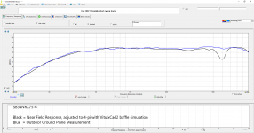
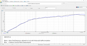
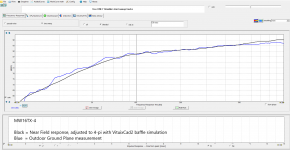
Hi Fluid... I was able to get nearfield results up to higher frequencies than what you mention. For a 12" woofer, I was able to go to 500 Hz. For a 6" driver I was able to go above 1000 Hz. The first 6" driver ground plane plot is with the cabinet on it's side, the second is a ground plane plot with the cabinet upright.
I don't have a plot to show on tweeters, but I recall that my nearfield tweeter measurements were valid up to about 5 kHz.
When I merge NF into gated FF measurements, I like to have a broad overlap between the two so I can make sure the final merged response makes sense. I also cross check the result with the full spectrum "blended" response. In ARTA, this is called a dual-gate measurement, I am not sure what it would be called in REW.
Nearfield measurements are valid somewhere up to 300 or 400Hz so it is the range from there up to about 800Hz where there is a significant loss in measurement resolution with short gates.
Hi Fluid... I was able to get nearfield results up to higher frequencies than what you mention. For a 12" woofer, I was able to go to 500 Hz. For a 6" driver I was able to go above 1000 Hz. The first 6" driver ground plane plot is with the cabinet on it's side, the second is a ground plane plot with the cabinet upright.
I don't have a plot to show on tweeters, but I recall that my nearfield tweeter measurements were valid up to about 5 kHz.
When I merge NF into gated FF measurements, I like to have a broad overlap between the two so I can make sure the final merged response makes sense. I also cross check the result with the full spectrum "blended" response. In ARTA, this is called a dual-gate measurement, I am not sure what it would be called in REW.
Attachments
Last edited:
I have seen this dual-gate measurement mentioned in the ARTA documentation, but I've not been able to understand it at all. Any explanation and help will be very nice.Fluid wrote:
Hi Fluid... I was able to get nearfield results up to higher frequencies than what you mention. For a 12" woofer, I was able to go to 500 Hz. For a 6" driver I was able to go above 1000 Hz. The first 6" driver ground plane plot is with the cabinet on it's side, the second is a ground plane plot with the cabinet upright.
I don't have a plot to show on tweeters, but I recall that my nearfield tweeter measurements were valid up to about 5 kHz.
When I merge NF into gated FF measurements, I like to have a broad overlap between the two so I can make sure the final merged response makes sense. I also cross check the result with the full spectrum "blended" response. In ARTA, this is called a dual-gate measurement, I am not sure what it would be called in REW.
Hi Fluid... I was able to get nearfield results up to higher frequencies than what you mention. For a 12" woofer, I was able to go to 500 Hz. For a 6" driver I was able to go above 1000 Hz. The first 6" driver ground plane plot is with the cabinet on it's side, the second is a ground plane plot with the cabinet upright.
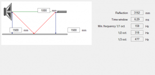
The premise of the nearfield technique developed by Don Keele is that at low frequencies the driver diaphragm acts like a rigid piston and the near-field measurement is directly proportional to the far field one and is not affected by the environment.
This holds while the driver has a Ka=1 which is the the diameter of the driver x pi / wavelength so to keep it at 1 the wavelength needs to equal the diameter x Pi.
For a theoretical 300mm driver this gives an upper frequency of 365Hz give or take.
If the driver behaves very much like a piston higher in frequency then the result maybe more valid higher up.
At low frequencies nearfield is very accurate, at high frequencies gated measurements are very accurate. It is the part in between where it gets fuzzy. It then becomes hard to know what you truly have without comparing it to a long gate time or more truly anechoic measurement.
I don't see any disagreement in this amongst Keele, Klippel, Aarts or any of the other researchers.
https://www.klippel.de/fileadmin/klippel/Files/Know_How/Application_Notes/AN_38_Nearfield_Measurement_with_Multiple_Drivers_%20and_Ports%282%29.pdf
https://www.klippel.de/fileadmin/klippel/Files/Know_How/Application_Notes/AN_39_Merging_Near_and_Farfield_Measurements.pdf
This makes sense, relative to my measurement results. My woofer has an effective Sd area of 508 cm^2, which is a diameter of 25.4 cm, so Ka=1 at 430 Hz. I was able to maintain good correlation just a little bit higher up to 500 hz, but I bet my phase was getting whacky at that point.
Same with the 6 inch driver: Sd = 119 cm^2, Dd = 12.3 cm, Ka=1 at 887 Hz, and again I showed good correlation a little bit higher up to ~ 1200 Hz.
I sometimes forget that drivers are often used above the first resonance mode. I have not done this on any of my recent designs, so it is easy to overlook the consequences. Yes, without a doubt the nearfield technique stops working as a driver approaches either the first diaphragm mode or a surround mode.
Thanks for the clarification.
j.
Yup. Totally.At low frequencies nearfield is very accurate, at high frequencies gated measurements are very accurate. It is the part in between where it gets fuzzy.
I have seen this dual-gate measurement mentioned in the ARTA documentation, but I've not been able to understand it at all. Any explanation and help will be very nice
I am no expert on the math behind the gated measurement technique. The last time I did a Fourier transform was 34 years ago at the university, with paper, pencil, and calculator. When I was setting up ARTA, I struggled a bit making sense of the relationship between sequence length, FFT size, and sampling rate... like I said, not an expert.
I believe that when ARTA does a dual gate measurement, it is processing the impulse signal twice: once with a 5 ms gate, and once with a 50 ms gate. The long gate allows measurements down to 20 Hz, but it also allows the room response to show up in the measurement. ARTA then blends together the frequency and phase responses from the two gated processings into a single FR and phase response curve.
I compared the OminMic "blended" response feature to the ARTA "dual gate" and they both produced almost the exact same response, so I assume that the OmniMic software is doing something very similar.
j.
Ivo says it is the same as MLSSA which is a time adaptive 1/3 octave band window. A bit like REW's Frequency dependent window but with two fixed times and fixed frequency bandwidth.
Section 6.1 in the ARTA manual has some information too
ARTA
http://www.mlssa.com/pdf/MLSSA-Brochure.pdf
Section 6.1 in the ARTA manual has some information too
ARTA
http://www.mlssa.com/pdf/MLSSA-Brochure.pdf
Some updates
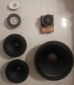
After an eternity, I am back to my workplace. And after lot of requesting, literally begging, and fighting with the SB distributor in the country, I have been able to get two more Satori WO24P-8 drivers. 😀
In the meanwhile, I got a chance to grab a 15inch Faital pro 15PR400-8 and an SB Audience Rosso-65CDN-T driver at bargain (clearance) prices. I just couldn't keep myself from buying a compression driver and the 15inch woofer seeing all the horn-related activities and threads on the forum. 😀
So now there are 2 projects. The existing 3 way active project and a 2 way project with the 15inch and CD on a horn (which has not been fixed at the moment). I am still studying about all this reading the different ongoing projects on the forum.
All the hardware for crossover and the drivers I have in hand now. Just need to get boxes and put them in.. 😀
I have requested some friends to help me with box building and they have started working on it. But it will take some more time due to their busy schedules.
For fun, I have attached a pc showing the driver collection. 😀
Thanks
Vineeth
Attachments

I have not gone back to review the whole thread, so apologies if this is a dumb question... are you using two WO24P woofers per speaker?
Hi..I have not gone back to review the whole thread, so apologies if this is a dumb question... are you using two WO24P woofers per speaker?
Yes. From the simulations that fluid did, we came to the conclusion that having 2 Satori WO24Ps per speaker was better in terms of directivity and other aspects.
Nice - that is a lot of bass capability, 500 cm^2 of area. I hope to have the opportunity to use that driver some day.
- Home
- Loudspeakers
- Multi-Way
- A 3 way design study