Hi Vineethkumar01,
No needs to apologize!
I have no issues with differents opinions than mine, but for things i studied ( humbly, i'm in no way an expert on this but it was part of my previous job so i have some basis) i know there is answers to be found if you look at the right places/field of interest. 😉
About the wwmt imho it is related to what Tmuikku/Fluid explained previously: interaction with room boundaries AND bandpass of said drivers.
Let's play a bit with the simulator in this link and draw your own conclusions about it:
SBIR calculator
It is way less attractive than some polar maps but will give a view of the issues and how by fixing listening location, drivers locations and playing with the room artefacts you can have interesting approach to it ( for multidrivers, make multiple iterations and compare results you'll see it is easy to simulate the issues you can face as the one Tmuikku have with floor /ceiling creating a wide range ( low Q) issue if the bounce happen simultaneously or close enough).
By selecting the location and driver bandpass wisely you can counteract some of the effects.
Layout play a role too and as i spent a lot of time studying some ( big) MTM it can help mitigate floor/ceiling bounce by spreading the issues: rather than one 'large' ( low Q) notch you can have more higher Q one on differents freq locations. Much less objectable as our brains are less sensible to high Q issues and even more when they are a notch rather than a boost.
Last edited:
Are you sure about this? Yes they do when the drivers are far enough, 300Hz is ~1.1m long and if drivers are further than 1/4wl apart, roughly 30cm, then there starts to be some difference but not sure it is too meaningful until closer to 1/2wl, say 50cm. Frequencies lower than 1/4wl c-c of the furthest drivers they would combine as single source and sound like one.
.....
As you see there is no difference below ~300Hz, it is all constructive interference since the wavelengths are so long compared to the distance between the drivers I think. The graphs are showing floor and ceiling reflection, no wall reflection. Here c-c between the furthest drivers is 40cm, roughly 1/3wl at 300Hz.
Horbach and Keele published a graph which explain your observation:
Figure 3 in the second part of the publication number 42 there:
AES Papers -- Official website of D.B.Keele
http://www.xlrtechs.com/dbkeele.com...ear Phase Digital Crossover Flters Part 2.pdf
I was confused for a longtime about choices made by Kinoshita ( for the RM range) or Jbl ( with K2 s9500 and others mtm) about drivers spacing ( because it doesn't follow the 1/4wl ctc rule strictly) until i saw this graph in fig 3.
My own experiments with mtm showed me it is the limit in real life application if you want omni 'behavior' ( you don't have acoustic coupling up to fc ( less level than for 1/4wl, in the range of 1/2 db from my experience) but you still feel the sound emanating from the 'virtual center' between drivers, without 'artificial stretching' of the image as i would put it into words once you 'break largely' the rule )) : 0.333 wavelength at fc is the limit. After that you start to 'beam forming' the outcome, which can be an advantage ( or not!).
This is the effects they ( Horbach/Keele) used with their FIR approach to maintain vertical directivity into a defined angle ( but it needs the particular shape of FIR they used for spaced pair and have other limitation with a single point source... as explained in the papers.).
Last edited:
Hi Vineethkumar01,
No needs to apologize!
I have no issues with differents opinions than mine, but for things i studied ( humbly, i'm in no way an expert on this but it was part of my previous job so i have some basis) i know there is answers to be found if you look at the right places/field of interest. 😉
About the wwmt imho it is related to what Tmuikku/Fluid explained previously: interaction with room boundaries AND bandpass of said drivers.
Let's play a bit with the simulator in this link and draw your own conclusions about it:
SBIR calculator
It is way less attractive than some polar maps but will give a view of the issues and how by fixing listening location, drivers locations and playing with the room artefacts you can have interesting approach to it ( for multidrivers, make multiple iterations and compare results you'll see it is easy to simulate the issues you can face as the one Tmuikku have with floor /ceiling creating a wide range of issue).
By selecting the location and driver bandpass wisely you can counteract some of the effects.
Layout play a role too and as i spent a lot of time studying some ( big) MTM it can help mitigate floor/ceiling bounce by spreading the issues: rather than one 'large' ( low Q) notch you can have more higher Q one on differents freq locations. Much less objectable as our brains are less sensible to high Q issues and even more when they are a notch rather than a boost.
Horbach and Keele published a graph which explain your observation:
Figure 3 in the second part of the publication number 42 there:
AES Papers -- Official website of D.B.Keele
http://www.xlrtechs.com/dbkeele.com...ear Phase Digital Crossover Flters Part 2.pdf
I was confused for a longtime about choices made by Kinoshita ( for the RM range) or Jbl ( with K2 s9500 and others mtm) about drivers spacing ( because it doesn't follow the 1/4wl ctc rule strictly) until i saw this graph in fig 3.
Thanks a lot krivium... 🙂
The links you have pointed look awesome to me... I am going to read those Keele papers first.. 😀 and play around with the calculator.
Then I will try things out with VituixCAD also and understand more about these things.. 🙂
So many things to learn... 😀
These days I am wondering whether I am getting more interested in the process of making speakers itself than in having the speaker and listening to it.. 😀 Hopefully, I will get around to doing both soon enough.. 😀
These days I am wondering whether I am getting more interested in the process of making speakers itself than in having the speaker and listening to it.. 😀 Hopefully, I will get around to doing both soon enough.. 😀
In my view both a theorical approach and realisation are needed.
Theory won't tell you how it 'sound' in real life and realisation without theory is either a shot in the dark, either pure luck if something sound nice, so impossible to reproduce or understand why it sound good.
There is less and less 'black art' in the design process and so much differents approach which 'works' in real life...
I agree studying the design and try to understand them is a great part of the joy in the process to me.
Maybe if i was good at woodworking ( as some members here are! So many jewell's projects!) i would enjoy as much the realisation part... but i'm not! 😡 😀
Box always end up as prototype uglyness! 😀
Last edited:
I'm not even sure what you are not sure about 🙂Are you sure about this?
You can see the shape of the combination of the two sources in the observation field above, the further you get away the more the two converge as one.
I'm not really sure what you're getting at with the rest. If you move a driver vertically then you will change the frequency at which any bounce from the floor or ceiling can cause an issue. The Allison approach was to mount the woofer lower to the floor and the mid high up and cross at about 300Hz so neither was outputting where a bounce could interfere. Same if you listen closer or further away things change.
I don't think a speaker with two woofers would sound remarkably different to just having one if kept loafing or subwoofers were going to be used at the low end. The biggest difference would come from doubling the volume displacement as you cannot really have enough of this. The spreading of the sources vertically is a minor but useful addition and certainly does not cause any harm.
Horbach and Keele published a graph which explain your observation:
Figure 3 in the second part of the publication number 42 there:
AES Papers -- Official website of D.B.Keele
http://www.xlrtechs.com/dbkeele.com...ear Phase Digital Crossover Flters Part 2.pdf
I was confused for a longtime about choices made by Kinoshita ( for the RM range) or Jbl ( with K2 s9500 and others mtm) about drivers spacing ( because it doesn't follow the 1/4wl ctc rule strictly) until i saw this graph in fig 3.
My own experiments with mtm showed me it is the limit in real life application if you want omni 'behavior' ( you don't have acoustic coupling up to fc ( less level than for 1/4wl, in the range of 1/2 db from my experience) but you still feel the sound emanating from the 'virtual center' between drivers, without 'artificial stretching' of the image as i would put it into words once you 'break largely' the rule )) : 0.333 wavelength at fc is the limit. After that you start to 'beam forming' the outcome, which can be an advantage ( or not!).
This is the effects they ( Horbach/Keele) used with their FIR approach to maintain vertical directivity into a defined angle ( but it needs the particular shape of FIR they used for spaced pair and have other limitation with a single point source... as explained in the papers.).
I wish I had time and patience to read all the texts written before 😀 Thanks posting the links, will try and read in the evening.
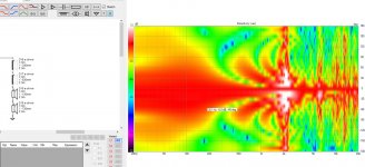
Since we headed into arrays I made another test to observe from. It looks like, for this particular case I've been playing with, to have vertical pattern control at 300Hz we need ~60cm c-c spacing between 8" drivers to get nominal 90 degree vertical dispersion at 300Hz. Anything less the pattern is so wide floor and ceiling reflections will affect. I find the flip side more interesting though, using two drivers to get pattern control gets into lobing and interference quite soon above the target frequency! So I see the benefit is slim in pattern control point of view, only maybe an octave usable narrowed vertical dispersion after which there is all kinds of lobes forming and ruining the joy. For this reason multiple drivers would be better as an array of many drivers than only two drivers at "the ends". Multiple drivers would add more lobing and average the pattern out.
Attachment 1. showing the -6db point at 45 degrees vertical ~300Hz and it is about 60cm driver spacing. Pattern is ~180 at ~200Hz. The polar map is normalized.
Attachment 2., the sixpack from the situation. Now there is severe dip already at the top end of the mid driver bandwidth, can't increase spacing any more. And, pretty bad interference below that already. See the now unnormalized vertical polar map, looks nasty from half way up.
ps. I'm not sure how much it affects that the mids are somewhat cardioidish down to the 200Hz, see the normalized horizontal polar map. I guess it doesn't make too much difference since the pattern is still way past 90Hz.
Attachments
Last edited:
Oncie more 😀
Exported the estimated in room response that has floor and ceiling bounce included, the orange curve. Then, imported it to calculator where there was smoothing function available. To my limited knowledge on psychoacoustics I think the 1/3 octave smoothing crudely imitates how the hearing system can ignore some of the high Q frequency response issues, especially dips.
Now, it looks like the floor / ceiling interference to the high frequencies roughly above few kilo Hertz is negligible. On the other end there would be the room modal region somewhere down to the 200Hz or what not. So, the wiggle on these smoothed inroom responses between say 200Hz and 2000Hz might be audible. I'm ignoring horizontal reflections completely, which propably would average things out, or make them even worse.
From this we could draw some kind of guide line for design help, if one wants to address the effect of the floor or ceiling bounce in the speaker design somehow. This would include having narrow dispersion < 90 degrees vertical on the 200Hz- 2kHz range, or, consider perhaps elevating the midrange driver so that the interference is least worst from 200Hz to say 800Hz where a waveguided tweeter could perhaps take control.
Anyway the possible issues of floor and ceiling bounce seem to lay on the 3-way system midrange driver bandwidth. Add in diffraction, enclosure resonances, port leakage, driver surround resonances and all other issues that mostly lie on this particular bandwidth as well not forgetting it is about the most sensitive region of the ear 😀 Maybe these all combined make statistically average okay sound 😀 Hmm, how would it sound to get rid all of these issues?😀
Attachments are:
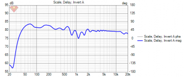
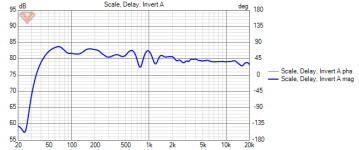
1. a sim of a speaker. The orange line is exported, it is in room response estimate with the floor and ceiling reflections.
2. This is the 1. in room response, 1/3 octave smoothing.
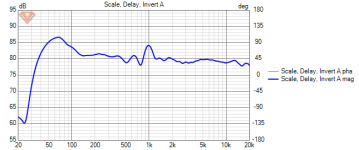
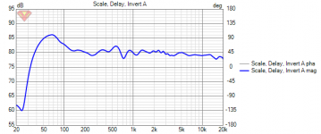
3. Here mid and tweeter are flipped making the WMT system to WTM
4. Here is back to WMT but now the mid and tweet are elevated higher up, about half room height.
Exported the estimated in room response that has floor and ceiling bounce included, the orange curve. Then, imported it to calculator where there was smoothing function available. To my limited knowledge on psychoacoustics I think the 1/3 octave smoothing crudely imitates how the hearing system can ignore some of the high Q frequency response issues, especially dips.
Now, it looks like the floor / ceiling interference to the high frequencies roughly above few kilo Hertz is negligible. On the other end there would be the room modal region somewhere down to the 200Hz or what not. So, the wiggle on these smoothed inroom responses between say 200Hz and 2000Hz might be audible. I'm ignoring horizontal reflections completely, which propably would average things out, or make them even worse.
From this we could draw some kind of guide line for design help, if one wants to address the effect of the floor or ceiling bounce in the speaker design somehow. This would include having narrow dispersion < 90 degrees vertical on the 200Hz- 2kHz range, or, consider perhaps elevating the midrange driver so that the interference is least worst from 200Hz to say 800Hz where a waveguided tweeter could perhaps take control.
Anyway the possible issues of floor and ceiling bounce seem to lay on the 3-way system midrange driver bandwidth. Add in diffraction, enclosure resonances, port leakage, driver surround resonances and all other issues that mostly lie on this particular bandwidth as well not forgetting it is about the most sensitive region of the ear 😀 Maybe these all combined make statistically average okay sound 😀 Hmm, how would it sound to get rid all of these issues?😀
Attachments are:
1. a sim of a speaker. The orange line is exported, it is in room response estimate with the floor and ceiling reflections.
2. This is the 1. in room response, 1/3 octave smoothing.
3. Here mid and tweeter are flipped making the WMT system to WTM
4. Here is back to WMT but now the mid and tweet are elevated higher up, about half room height.
Attachments
Last edited:
So you see why some of us have never acknowledged this as a 'rule', more a suggestion. Of course setting this beamwidth is only the tip of the iceberg in getting the crossover region to mimic the rest of the system.because it doesn't follow the 1/4wl ctc rule strictly
I'm not even sure what you are not sure about 🙂
Trying to observe how using multiple woofers on a three way would affect pattern and implications of the pattern 🙂
I'm not really sure what you're getting at with the rest. If you move a driver vertically then you will change the frequency at which any bounce from the floor or ceiling can cause an issue. The Allison approach was to mount the woofer lower to the floor and the mid high up and cross at about 300Hz so neither was outputting where a bounce could interfere. Same if you listen closer or further away things change.
I don't think a speaker with two woofers would sound remarkably different to just having one if kept loafing or subwoofers were going to be used at the low end. The biggest difference would come from doubling the volume displacement as you cannot really have enough of this. The spreading of the sources vertically is a minor but useful addition and certainly does not cause any harm.
Exacto, there is benefit using multiple woofers, more SD and less excursion and slimmer cabinet and what not. Nothing to do with pattern control though, other than what the distance to mid driver makes. Actually there is some pattern control, but it doesn't seem to be meaningful. The array should be longer than listening height and even then there would soon be problems bit higher in frequency so no win for floor and ceiling bounce unless the array approaches full room height. This is my conclusion from the experiments.
Not sure if any of it has relevance for the project, very interesting though 🙂 The knowledge might benefit on some instances at least.
ps. I see, I'm using mid drivers to demonstrate and then speak about bass and woofers! it is bit confusing! sorry, my Finnish Savonian thought process is faster than my english typing finger 😀 Both bass and mid data can be evaluated from the graphs within the context of the experiments.
Last edited:
negating my own words a bit, there might be very good use case if the woofer array had narrow dispersion below the 300hz to say 200hz or something. would still be under a meter tall i think. need to test later. thos could eqialize sound between large and small rooms for example?
Last edited:
Hi Allen,
I see this as a rule as it was taught like that to me: when studying basic of acoustic/loudspeaker my teacher was really into acoustic coupling phenomenon which is true at 1/4 wl relationship.
As some members here emphasized this as a rule, i took ( and still take) it like this.
But yes it can be stretched somewhat.
In my view both a theorical approach and realisation are needed.
Theory won't tell you how it 'sound' in real life and realisation without theory is either a shot in the dark, either pure luck if something sound nice, so impossible to reproduce or understand why it sound good.
There is less and less 'black art' in the design process and so much differents approach which 'works' in real life...
I agree studying the design and try to understand them is a great part of the joy in the process to me.
Maybe if i was good at woodworking ( as some members here are! So many jewell's projects!) i would enjoy as much the realisation part... but i'm not! 😡 😀
Box always end up as prototype uglyness! 😀
Totally, very much fun for us engineer minded just to think about all the interplay that goes into a loudspeaker and try to get the chaos into some kind of balance 😀 From outside a hobby like this must seems silly I believe... when ever my friends talk about stuff that is even remotely connected to music reproduction they talk about how to get rid of all the cables in the house. Talking about directivity or modes makes them run away 😀
Last edited:
@krivium, 90 degrees is significant, it is usually described in electronics terms. This does translate to speakers in some ways, maybe not all.
If you put one speaker 3m to your right and one to your left, then put a mic between them you'll still measure +6dB, so what has coupled?
If you put one speaker 3m to your right and one to your left, then put a mic between them you'll still measure +6dB, so what has coupled?
Hi Allen,
I see this as a rule as it was taught like that to me: when studying basic of acoustic/loudspeaker my teacher was really into acoustic coupling phenomenon which is true at 1/4 wl relationship.
As some members here emphasized this as a rule, i took ( and still take) it like this.
But yes it can be stretched somewhat.
For this reason I've lately written every measure as approximation or rough number since much of the stuff has some slack to adjust anyway and for example a centimeter down in bass region means nothing but at treble it is very meaningful unit of length, even millimeters are relevant high up. In contrast relative lenghts like 1/4wl are very handy, they get reader/discussion into the ballpark rather nicely regardles of frequency.
Watching stuff happen in the simulator by sweeping parameters with mouse wheel makes even the rough relative numbers irrelevant until one has to communicate the stuff with others, or translate text/ideas to simulations.
Last edited:
Isn't the gain 3db rather than 6 when you double the number of loudspeakers ( at least outside and not infinite baffle or approximation- sub on the floor)?
But i get your point Allen.
Tmuikku, yes those are approximations, no doubt. But as you stated it help to order chaos ( or see the underlying trends). Maybe the world is too much chaos for my brain and i need something to catch hoping for some less frightning reality? 😀
But i get your point Allen.
Tmuikku, yes those are approximations, no doubt. But as you stated it help to order chaos ( or see the underlying trends). Maybe the world is too much chaos for my brain and i need something to catch hoping for some less frightning reality? 😀
Last edited:
^Try tuning VituixCAD sims, takes you outta here for a moment 😀 Chaotic wiggles turn into interplay of orderly things as you tune the parameters, suddenly it is quite easy to figure out what is going on. Cant see a camouflaged animal either, until she starts to move.
The stuff I write is very clear to me due to the tweaking and seeing the lines change on the sim but I think it must be hard to follow my text since it is not very evolved and curated. My texts are more like pink live stream from the simulator observations to mediocre english transliteration 😀
I challenge evereyone to popup a simulator when there is interesting topic going on and try the stuff out, very powerful way to figure out what is going on. No need for math or too much theory, very light weight stuff to visualize.
Last edited:
@krivium, 90 degrees is significant, it is usually described in electronics terms. This does translate to speakers in some ways, maybe not all.
If you put one speaker 3m to your right and one to your left, then put a mic between them you'll still measure +6dB, so what has coupled?
Relevant post from Tom Danley
Do high-efficiency speakers really have better 'dynamics'? | Page 11 | Audio Science Review (ASR) Forum

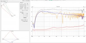
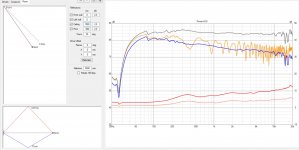
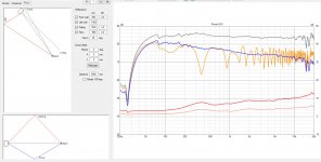
Alright one more test, which I think is interesting.
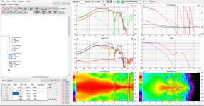
Attachment 1. a 3-way WMT system in a room, Both vertical and horizontal reflections are included in the in-room estimate, the orange line. Big dip around 400Hz
Attachments 2. and 3, the ~400Hz dip due to floor and ceiling pretty much persists when the speaker position relative to walls is changed. Be it corner or way out in the room the dip persists.* This makes me believe the ceiling and floor bounce is real issue and hidden if looking at the CTA-2034 standard PIR line only.
Attachment 4. There was some position where the front and side wall reflection could fill in the ceiling / floor dip at around 400Hz.
Attachments 5. and 6. are some of "the best" 1/3octave smoothed in-room estimates I was able to tweak out by tuning the room tab parameters and the mid height relative to listening height. I'm not sure if these are any better than other positions in reality but the noticeable thing is that the ~1kHz region is almost impossible to tame with the first reflections on in VituixCAD room -tab. If you check out these smoothed graphs and the ones in the previous post #247, they all have them. This would suggest that narrow pattern on the driver that covers the ~1kHz area would be the most important thing if a loudspeaker was to address the interference of the room. This would be easiest to achieve with a waveguide, at least in my system keeping it WMT.
* Notice how the listening position is attached to the speaker position and not to the simulated room corner in the simulations. This would not happen in reality, the listening position would likely to stay put while the speaker position was changed 😀
Attachments

Last edited:
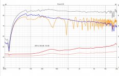
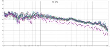
A good image from Floyd Toole's Sound Reproduction
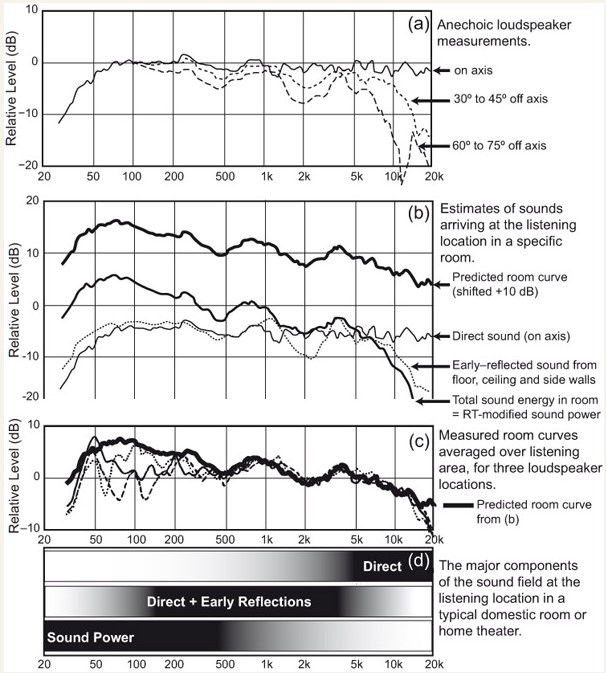
In the last graph I see that at 1k the differences in in room position have settled down to a pretty steady level, above 1K the speaker is almost completely in control
This corresponds very well to some of my own in room measurements where there is a clear knee in the response at 1K when you vector average the responses.

I love simulations and the right ones help immensely to understand what is happening in a way that is difficult to do in reality.
They rely on assumptions and the data fed into them as well as the questions being asked. If any of the are off the result is invalid.
In the last graph I see that at 1k the differences in in room position have settled down to a pretty steady level, above 1K the speaker is almost completely in control
This corresponds very well to some of my own in room measurements where there is a clear knee in the response at 1K when you vector average the responses.
I love simulations and the right ones help immensely to understand what is happening in a way that is difficult to do in reality.
They rely on assumptions and the data fed into them as well as the questions being asked. If any of the are off the result is invalid.
Attachments
Thanks, this helps make the point. It's somewhat like the issue of leakage inductance in a transformer.. but not about speaker coupling so much as it is about spatial commonality. It's in that regard that a real speaker becomes unique when not within 1/4wl, but there is otherwise no magic effect being missed out on.Relevant post from Tom Danley
- Home
- Loudspeakers
- Multi-Way
- A 3 way design study