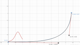
The above waveguide in an elliptical enclosure with edge rounding formed using below shown cubic bezier curve


Vertical is excluded from below directivity measurement due to lack of rounding on top and bottom edges in the sim

Dotted curves below are the DIs with the above enclosure with cuboidal cabinet.
Solid curves overlayed on it are the ones from the elliptical back enclosure

I think I have come to the conclusion for this build. I am going to make the MEH using the waveguide and cuboidal enclosure in previous post..
I am not getting enough returns (in terms of simulation results) with complex enclosures and complex edge termination profiles with this particular waveguide..
Maybe it is time to build one and hear how it all comes together in terms of sound..
I will try to get the waveguide 3D printed first.. 🙂
Vertical is excluded from below directivity measurement due to lack of rounding on top and bottom edges in the sim
Dotted curves below are the DIs with the above enclosure with cuboidal cabinet.
Solid curves overlayed on it are the ones from the elliptical back enclosure
I think I have come to the conclusion for this build. I am going to make the MEH using the waveguide and cuboidal enclosure in previous post..
I am not getting enough returns (in terms of simulation results) with complex enclosures and complex edge termination profiles with this particular waveguide..
Maybe it is time to build one and hear how it all comes together in terms of sound..
I will try to get the waveguide 3D printed first.. 🙂
Just because of OCD that I couldn't leave that super elliptic (SE) termination I made earlier alone, I approximated that SE termination with a cubic bezier
curve as shown below and simulated in ABEC
The black curve below (approximation) is right on top of the blue curve (original SE termination)


Here are the results

Bottom line: conclusions dont change from above.. 🙂
curve as shown below and simulated in ABEC
The black curve below (approximation) is right on top of the blue curve (original SE termination)
Here are the results
Bottom line: conclusions dont change from above.. 🙂
Attachments
I did the cad design for this MEH waveguide..
Here is a view from the bottom

Here is one from the top

Looks like some alien space ship I think.. 😀
Honestly speaking, all those "holes"/mid ports near the throat are not very confidence inspiring..
I thought I will print one more prototype and measure with the drivers I have before I move to final printing.. 🙂
Here is a view from the bottom
Here is one from the top
Looks like some alien space ship I think.. 😀
Honestly speaking, all those "holes"/mid ports near the throat are not very confidence inspiring..
I thought I will print one more prototype and measure with the drivers I have before I move to final printing.. 🙂
Just random things..
Super elliptic curves on the speaker cabinet.. They look nice.. 😀
View attachment 1340462View attachment 1340459View attachment 1340460
The above picture is a cabinet work and lacquering made by my friend. I designed this cabinet for Manger MSW but never completed:
I got the Bigger MEH waveguide printed, attached it to a cardboard box and took some quick and dirty measurements 🙂

Here is an on axis response plot of the DE 360 on the waveguide in 3 cases
1) All mid ports open (red, lot of wiggles)
2) Side mid ports closed (green, much less wiggles)
3) All mid ports closed (blue, slightly better than above but not by much)

I ended up using only the two drivers on top and bottom connected in parallel (and not the two on sides) because of response anomalies due to the holes in the sidewalls (mid ports) near the throat
Pic taken before closing side wall ports


DE 360 polars out to 90 degrees (normalization done 20 degrees off axis)

4NDF mid polars out to 90 degrees (normalization done 20 degrees off axis)

A first cut crossover


Impedance plots of the mids in parallel and DE 360, all drivers attached to the horn

Even with the issues due to resonances and other anomalies due to the flimsy cabinet construction, this look like good results I think
It feels like this MEH idea is worth pursuing.. 🙂
Here is an on axis response plot of the DE 360 on the waveguide in 3 cases
1) All mid ports open (red, lot of wiggles)
2) Side mid ports closed (green, much less wiggles)
3) All mid ports closed (blue, slightly better than above but not by much)
I ended up using only the two drivers on top and bottom connected in parallel (and not the two on sides) because of response anomalies due to the holes in the sidewalls (mid ports) near the throat
Pic taken before closing side wall ports
DE 360 polars out to 90 degrees (normalization done 20 degrees off axis)
4NDF mid polars out to 90 degrees (normalization done 20 degrees off axis)
A first cut crossover
Impedance plots of the mids in parallel and DE 360, all drivers attached to the horn
Even with the issues due to resonances and other anomalies due to the flimsy cabinet construction, this look like good results I think
It feels like this MEH idea is worth pursuing.. 🙂
Yeah! Very little effect from the taps, quite nice response!
Edge diffraction seems better as well, nothing obvious visible. Didn't revisit the previous waveguide measurements but it's likely better now 🙂
Edge diffraction seems better as well, nothing obvious visible. Didn't revisit the previous waveguide measurements but it's likely better now 🙂
Vineeth's proto looks much better to me than this super-directive monitor

https://reflectoraudiousa.com/
https://www.audiosciencereview.com/...coaxial-horn-monitor-with-4x-5-woofers.29072/
https://www.soundonsound.com/reviews/reflector-audio-square-two
https://reflectoraudiousa.com/
https://www.audiosciencereview.com/...coaxial-horn-monitor-with-4x-5-woofers.29072/
https://www.soundonsound.com/reviews/reflector-audio-square-two
REW autoEQ'd response of the DE 360 CD on horn and the burst decay


Looked like this was interesting.. 😀
Here is a comparison of the normalised sound power DI between the BEM sims I made and the measured results (only using 0 to 90 degree measurements).
Dotted line below is the SP DI from SIM
solid line is from actual measurements..

Looks really close I think.. 😲
Here is a comparison of the normalised sound power DI between the BEM sims I made and the measured results (only using 0 to 90 degree measurements).
Dotted line below is the SP DI from SIM
solid line is from actual measurements..
Looks really close I think.. 😲
Finally a MEH with vertically positioned ports. Seems to be a straightforward way to improve FR. I guess some efficiency could be regained if needed by using one size larger mid cones (if still fits on the WG) with strong motors and custom phase plugs to maintain bandwidth. I guess 2x air velocity on the ports for the same SPL is probably is not yet an issue. Going for only 1 port (say on the bottom) would require a 8" cone to match 4x 4" cones, something like the B&C 8PE21. That would be too large to place it on the wall of the WG, would need its own chamber behind and connect to the WG with a duct, maybe something like what is shown here 🙂 https://audioxpress.com/article/pat...with-damping-for-improved-speaker-performance
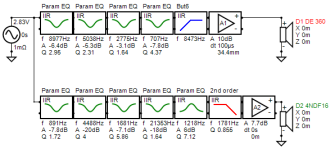
Attempt at a passive crossover just for fun.. 🙂


(The buffers in above plot are just to model the sensitivity differences, since I accidentally turned the volume control between measuring the two drivers)
(The buffers in above plot are just to model the sensitivity differences, since I accidentally turned the volume control between measuring the two drivers)
Last edited:
With the above passive crossover, the crossover frequency is somewhere around 1150Hz

For such low crossover, maybe a more robust compression driver is needed I guess.
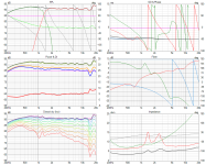
Below is the distortion profile of the DE 360 I measured on this horn (Probably not very accurate but shows the relative trends)

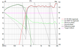
Anyway, I am happy with this active crossover, where the crossover frequency looks is 1350Hz


In that region the THD has climbed to only 0.2% and the driver is rolling off at 36dB per octave due to the effective high pass roll off

I think I probably need to look into phase related aspects also with the crossover, given that it is an MEH..
For such low crossover, maybe a more robust compression driver is needed I guess.
Below is the distortion profile of the DE 360 I measured on this horn (Probably not very accurate but shows the relative trends)
Anyway, I am happy with this active crossover, where the crossover frequency looks is 1350Hz
In that region the THD has climbed to only 0.2% and the driver is rolling off at 36dB per octave due to the effective high pass roll off
I think I probably need to look into phase related aspects also with the crossover, given that it is an MEH..
Attachments
Last edited:
Just applying response inversion tricks for full range FIR filtering and 8th order Linkwitz-Riley filters at 1350Hz..


Now I am done.. 😀
Based on the lessons learnt so far, I should probably plan to get the final printing of a pair of these waveguides with two drivers per waveguide done.. 🙂
Now I am done.. 😀
Based on the lessons learnt so far, I should probably plan to get the final printing of a pair of these waveguides with two drivers per waveguide done.. 🙂
One last attempt to have the MEH waveguide accommodate all the 4 x 4NDF3416 drivers (in parallel) 🙂


This time, enhancements to the older design includes the following
1) All 4 mid ports (1 for each driver) are vertically oriented and close to the corners
2) Mid ports closer to throat than earlier
2) Mid port opening more upto into each mid driver's centre region
One trade off is a slightly longer port than earlier (by about 10mm).. Not sure if it will cause much issues..
Distortion in woofers above 1kHz comes pretty much from cone resonances in 3-6kHz range. Then naturally a serial coil will reduce distortion above 1kHz because it is 1st orfer lowpass filter
View attachment 1314514
ps. distortion as % of fundamental would eliminate spl variation effect.... I have measured my project drivers with and without eq qnd xo many times and I don't believe that a serial coil would give lower distortion than dsp
You misunderstanding the test, it's in % with EQ flat in all case including with serial coil :
The SPL is the same on all bandwith in all case, all driver, with or without inductor, it's not due to a lower SPL due to a 1st order lowpass filter... The SPL is the same on all the bandwith.In essence: We use Back Electromotive Force principle with an air core inductor that will increase gradually the impedance (affecting the voice coil) and linearize the woofer in the same time, it works very well if the woofer is already rising up in his final box and need linearisation.
It will reduce a lot H3 and H5 distortion related to breakup.
Distortion measurements are done at 25cm 98dB, all drivers are EQ flat to be compared : The SPL is the same on all the bandwidth, for all drivers, with and without air core inductor, the difference with and without air core inductor is not due to SPL but to Back Electromotive Force principle, as explained in our dedicated article.
It's an eletro mechanical principle, everything is here : https://audiohorn.net/sciences/speaker-break-up/, on french forum most of the peoples now use serial core in active filtering to linearize the woofer with a passive components and not with a digital filter, it's related to BEF and motor inductance, it only work if the woofer rise up in frequencies in the box of course but there is also the notch technics that also play with inductance, for example it can be used on a RS52 as in the article.
If you have questions about it don't hesitate.
Last edited:
I have been trying to add a back cover to the MEH.. just some other shape other than a plain box... 🙂
This is based on the earlier observation that other than the overall depth of the backside, the low frequency directivity didn't care between plain old box and a more rounded elliptical backside.. Still I dont know how much impact this kind of shape will have..
Here are some pics of the MEH with and without the back cover


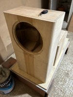
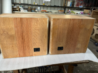
In other news, the enclosures are ready.. just needs some edge rounding (just for looks) and some painting and veneer finishing 🙂
Box for the 15PR400

Box for the SBaudience NERO SW800

Boxes stacked one on top of the other


This is based on the earlier observation that other than the overall depth of the backside, the low frequency directivity didn't care between plain old box and a more rounded elliptical backside.. Still I dont know how much impact this kind of shape will have..
Here are some pics of the MEH with and without the back cover
In other news, the enclosures are ready.. just needs some edge rounding (just for looks) and some painting and veneer finishing 🙂
Box for the 15PR400
Box for the SBaudience NERO SW800
Boxes stacked one on top of the other
Vineeth -- it's not clear what you're fighting with the 2 or 4 drivers to me. There's quite a bit going on at once. I'm no MEH wizard, but skim Chris' two posts starting here. And the screenie of Olson referenced in his post:
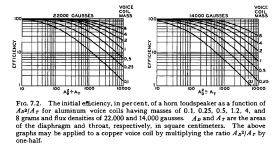
Secondly, to the extent it's still a horn, the rear chamber resonance and the front chamber resonances interact. It's all touchy, too, if you're trying to extract the most bandwidth out of the top.
What I wonder is if it makes sense to quick plug that stuff into HR and try to fake a conical MEH that's as close an approximation as you can make. You can learn a lot in a hurry messing with chamber sizing. Even if the two exact resonances are wrong, you can get a solid qualitative feel for how large their effect is and how squirrelly it all can be.
Thanks @grindstone 🙂
I have been caught up with so much work I haven't done much else in sometime.. I will once again go through the links you pointed out above..
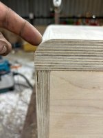
In the meanwhile, the cabinets for the woofers are slowly coming together. Here are the results after edge roundovers


I have been caught up with so much work I haven't done much else in sometime.. I will once again go through the links you pointed out above..
In the meanwhile, the cabinets for the woofers are slowly coming together. Here are the results after edge roundovers
Attachments
- Home
- Loudspeakers
- Multi-Way
- A 3 way design study
