When I decided to build this amp, several years ago, I wanted to make an amp with the best performance that can be done in DIY mode. So from the beginning there was no problem of using bjts due to frequency constraints. Using fets, the frequency band was ok, but the distortions due to too high Ugs and a small transconductance (which characterizes fets) were too high. So I decided to build the Hawksford error correction developed by Bob Cordell. I must mention that I have built several versions of this corrector, but for those who want to experience various variations on this theme, it should be known that the one published in Cordell's book is the best. Because the amp is not for commercial purposes, i.e. I am not interested in very high power, I supplied it with +-95V so as not to exceed the maximum voltage of the fets. I limited the output signal to +-65V. I also calculated the short-circuit limitation at a load of 2 ohms. Another thing. Fets have a quiescent current of about 160 mA. At a supply of +-95 V and a total quiescent current of 4*160mA, a very high dissipation results. And then I decided to build eengine. But with this I greatly reduced the performance of the amp. And then I inserted diodes D8 and D17. The result can be seen in the rise times in the oscillograms above. Because the work is in progress, if anyone has comments, suggestions or observations, they are welcome.
Last edited:

use 50hz signal from youtubeHow to test step by ic irs2117
I gave 50hz but stepper not work only ab class mode work.out put ac volts only gets 30v ac max..thanks
I see that the two circuits are not really the same... I see that there are quite a few pieces on yours. Can you reveal your scheme to us?
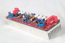
exactly there are not the same, my version base schematic is nearly close to the original one Labg. fp10k series.. delay and dc protect is not the original one, input balance, clip limiter, vi liimiter are based on how the original one work but made it simple... too many protecton in the original that not fit into the board, hi freq. protection, average current limit are omirtedI see that the two circuits are not really the same... I see that there are quite a few pieces on yours. Can you reveal your scheme to us?
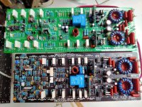
this is my prototype test, supply +-90vdc ct , standby no signal +9v postive rail , -9.v negative rail, 0.1v dco.
Very nice. Why did you choose to make a design based on Labgruppen and not on Yamaha? I saw that you supplied only +-90V. Didn't you build it for high power? It would have been interesting to share the schematic with us and discuss the details of this amp, but you probably built it for commercial purposes, so that's it.
i've made both of Tracking Down topology Eeeninge (yamaha) and Labgruppen.Very nice. Why did you choose to make a design based on Labgruppen and not on Yamaha? I saw that you supplied only +-90V. Didn't you build it for high power? It would have been interesting to share the schematic with us and discuss the details of this amp, but you probably built it for commercial purposes, so that's it.
Yamaha need more transistor, for final and volt buffer.
Labgruppen don't have volt buffer.
and +-90 vdc ct supply just for testing the prototype... actually it will supplied from +-168vdc ct up to +-180vdc ct.. could be up to +-198vdc ct if using mjl2119x for final transistor (just like fp14000).
"actually it will supplied from +-168vdc ct up to +-180vdc ct.. could be up to +-198vdc ct if using mjl2119x for final transistor (just like fp14000)."
Why not mjl4281 / mjl4302 ?
"Labgruppen don't have volt buffer."
Well, that's exactly the problem. The frequency response is given by the tracking source.
Why not mjl4281 / mjl4302 ?
"Labgruppen don't have volt buffer."
Well, that's exactly the problem. The frequency response is given by the tracking source.
mjl4821/4302 used as driver in original."actually it will supplied from +-168vdc ct up to +-180vdc ct.. could be up to +-198vdc ct if using mjl2119x for final transistor (just like fp14000)."
Why not mjl4281 / mjl4302 ?
"Labgruppen don't have volt buffer."
Well, that's exactly the problem. The frequency response is given by the tracking source.
from what i've experienced by build this two topolofy (yamaha and labgruppen)
yamaha have good high freq. response otherwise Labg. have good low freq. response.
if you want good mid high freq. response go for yamaha.
it's easier to build yamaha than labgruppen.
All the H900 from Mile i've made with IR have never disappointed. The IRs are usually very responsive and voltage rises nicely with signal, a very efficient amp. Who can help me build H900 as three tier please? who knows how I can adapt the 3 tier Vertex to a H900?
https://www.diyaudio.com/community/threads/andrew-lebon.400145/post-7372670hi apexaudio
greetings cool pcb would be a great diy project for h class diyers
keep up the goodwork
thanking you
andrew lebon
this is tragic r.i.p to andrew lebon who participated in this topic . we will miss you andrew 😢
- Home
- Amplifiers
- Solid State
- 900W H-class PA Amp with Limiter