possible diy error
1.pcb error short or miss
2.wrong value component installing or defective or wrong alternative or reverse
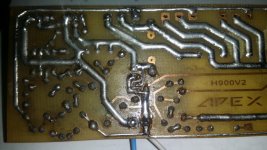
first check voltage between hv and mv.after five min. check voltage on mur diode(no load condition) if voltage not same on both pin of diode it mean stepper not good. you should change 15 v ziner diode of stepper circuit some time ziner looking good with meter but they change there value.if you use any alternative then ask to expert apex then go forward.hope it is useful.
1.pcb error short or miss
2.wrong value component installing or defective or wrong alternative or reverse
first check voltage between hv and mv.after five min. check voltage on mur diode(no load condition) if voltage not same on both pin of diode it mean stepper not good. you should change 15 v ziner diode of stepper circuit some time ziner looking good with meter but they change there value.if you use any alternative then ask to expert apex then go forward.hope it is useful.
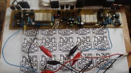
check you capacitor conenetion again i doubt you did wrong connection that why your volatge droping and your ground wire is not right.
hi apex sir,i want to make disply pannel(power ,clip,signal,protect) for h900.please give me some hint.
hi apex sir,i want to make disply pannel(power ,clip,signal,protect) for h900.please give me some hint.
post #74
http://www.diyaudio.com/forums/solid-state/243345-current-dumping-amplifier-8.html
will you share your all pcb files?h1200,h1200 v3 and h900
thank apex audio.
havia I already noticed. but I could not edit my post, so it was left without modificar.solo was by ultra fast diodes.
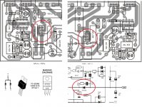
Hello Mr. Apex.. i need your opinion for using mur1620 and PCB V2.
As i understand with the diode schematic i have... V2 PCB is not suited
for my MUR1620... shall i reverse the connection base on the schematic? hoping for your reply.. thanks and regards
Attachments
Hello Mr. Apex.. i need your opinion for using mur1620 and PCB V2.
As i understand with the diode schematic i have... V2 PCB is not suited
for my MUR1620... shall i reverse the connection base on the schematic? hoping for your reply.. thanks and regards
Im doing test right now...
Attachments
you are no. first lol .pull that diodes and replace with mur1660ct.then enjoy.Hello Mr. Apex.. i need your opinion for using mur1620 and PCB V2.
As i understand with the diode schematic i have... V2 PCB is not suited
for my MUR1620... shall i reverse the connection base on the schematic? hoping for your reply.. thanks and regards
you are no. first lol .pull that diodes and replace with mur1660ct.then enjoy.
Thanks for your reply rohin... i sure u miss understood me wen u say lol. reversing connection doesn't men just saying turning literally the diode. I mean only to say the connection from anode to cathode of the mur1620 should be fitted according to Apex schematics of H900..
Regards
Thanks for your reply rohin... i sure u miss understood me wen u say lol. reversing connection doesn't men just saying turning literally the diode. I mean only to say the connection from anode to cathode of the mur1620 should be fitted according to Apex schematics of H900..
Regards
This is what i did..
Attachments
sorry for mis understanding but that word not for you.i didn't see your name.now forget this.Thanks for your reply rohin... i sure u miss understood me wen u say lol. reversing connection doesn't men just saying turning literally the diode. I mean only to say the connection from anode to cathode of the mur1620 should be fitted according to Apex schematics of H900..
Regards
difference not in that number.difference in ct and ctr.actually difference in positive negative check pin out. he may be didn't get that diodes.Why a mur1660 instead of mur1620?
sorry for mis understanding but that word not for you.i didn't see your name.now forget this.
Pls dont worry Friend... not an issue... 🙂
Best Regards
- Home
- Amplifiers
- Solid State
- 900W H-class PA Amp with Limiter